Maintenance procedures 3-57
3. Start the pump, setting the flow rate to 0.1 mL/min. Run it until the
indicator rod retracts fully into the pump head.
4. Shut down the pump.
5. Loosen the nut that secures the outlet line from the outlet check valve,
then disconnect the line.
6. Remove the two hex-head screws with a 5/32-inch hex wrench. Slide the
pump head assembly straight off the pump.
Tip: If you are replacing the pump seal, continue with the procedure in
“Replacing the pump seal” on page 3-58.
Tip: If you are replacing the pump plunger or the wash seal, refer to the next
procedure to remove the head support assembly.
Removing the head support assembly
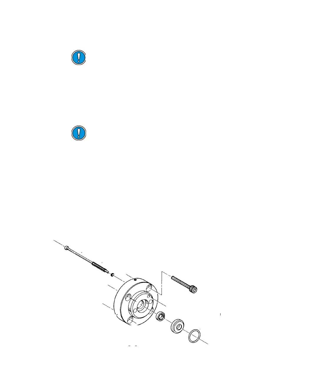
The figure below is an exploded diagram of the head support assembly.
Head support disassembly
Caution: The indicator rod must be fully retracted into the pump
head. Otherwise, the plunger can sustain damage.
Caution: Causing the pump head to bind against the plunger can
break the plunger.
SPRING
TEFLON WASHER
HEAD SUPPORT
BUSHING
O - RIN
RETAINER
ALLEN SCREWS (4)
Indicator rod
Spring
Teflon washer
Hex-head screw (4)
Retainer
O-ring
Wash seal
Head support
bushing