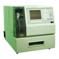
Waters Prep series 1-11
withdraw the samples means the autoinjector must generate the analysis
start signal when the sample is ready for injection.
The rear panel strip also contains these items:
Signal ground – Terminals labeled Gnd should reference all controller
digital input and output signals. Ground terminals should be connected
together among system modules.
Chassis ground – Internally connected to the controller’s chassis. These
terminals connect the shield lead from an analog signal cable, like the one
used with the Press or Chart analog output signals.
+12 V supply – A terminal on the controller carries up to 1.2 A of current at
+12 VDC. It is used with event output switches S1 to S4 for actuating solenoid
valves and other automation accessories.
AC power connector – Houses fuses and the inlet connection for the power
supply cord. It also provides for selecting operating voltage.
Auxiliary power fuse – Contains a 1.5-A fuse for the +12 VAC accessory
power terminal.
Pump power fuse – Contains a 4-A fuse (5 × 20 mm).
Connecting cables
System interface – Thirty-seven pin connector that allows system
communication between the controller and the fluid handling unit.
IEEE-488 – Allows communication interface between system controller and
PowerLine detectors and autoinjectors.
RS-232 – Allows communication interface for Waters 746 integrator or
Waters MassLynx™ or Empower™ workstations.
Injectors
Use the Rheodyne 3725i injector for large-scale separations and the 7725i
model for small-scale ones. Both injectors let you load sample by syringe
(injecting it into the injector) or suction (attaching the syringe to a vent tube
and drawing it through the loop).
Rheodyne 7725i injector (Delta-Prep system)
The Rheodyne 7725i injector incorporates a 100-µL fixed sample loop. The
loop and valve passages together form the 100-µL volume. This injector is for
small-scale separations.