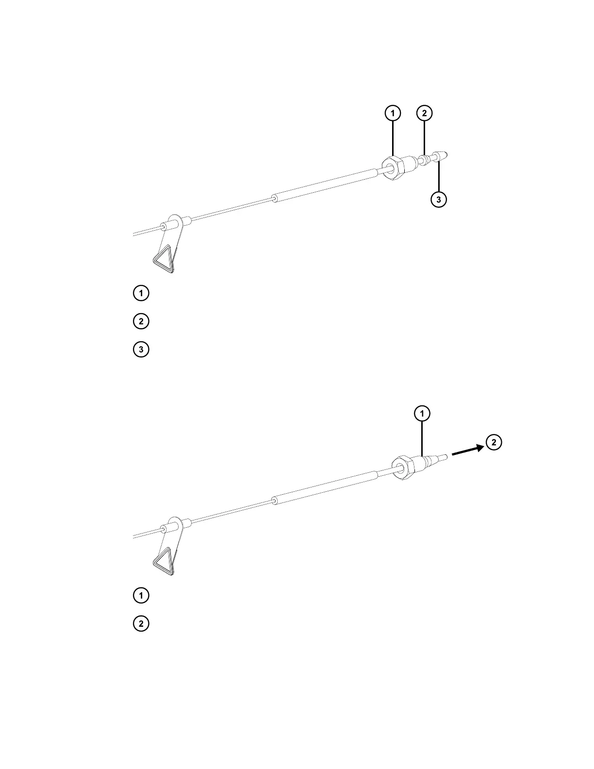
Figure 3–20: Fitting the compression nut, backing ring, and ferrule to the probe
assembly
Compression nut
Backing ring
Ferrule
2. Insert the probe assembly into the ISM's restrictor port until you encounter resistance.
Figure 3–21: Connecting the probe assembly to the ISM
Compression nut, backing ring, and ferrule
To ISM restrictor port
3. Slide the compression nut, backing ring, and ferrule into the restrictor port.
4. Using your fingers, screw the compression nut into the splitter port until you feel resistance.
January 10, 2022, 715006200 Ver. 01 (previously released as Rev. A)
Page 63