Do you have a question about the Waters TQ Detector and is the answer not in the manual?
Find contact details and locations for Waters Corporation on their official website.
Contact Waters Corporation using telephone and fax numbers provided for inquiries.
Mailing address for Waters Corporation for correspondence and support.
Addresses the risk of solvent leakage from the TQ Detector's exhaust system and O-ring integrity.
Details safety precautions for using flammable solvents with the TQ Detector, including nitrogen flow.
Warning about burn injuries from touching hot surfaces of the TQ Detector.
General advisories for instrument safety, referring to appendix for detailed warnings.
Explanation of symbols used in the manual and on the instrument.
Defines the purpose of the TQ Detector as a research tool, not for diagnostic applications.
Procedure for calibrating LC systems using standards to generate a curve.
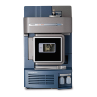
General description of the instrument, controls, and plumbing connections.
Explanation of IntelliStart technology for monitoring and optimizing LC/MS/MS performance.
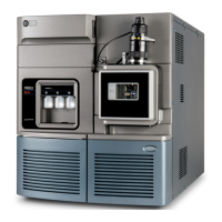
Details on the ACQUITY TQD system, including the UPLC and TQ Detector integration.
Overview of the ACQUITY UPLC system, its modules, and control software.
Information on Empower and MassLynx software for instrument control and data management.
Description of the ACQUITY UPLC Console application for system configuration and monitoring.
Explanation of the ESI process for generating ions from liquid samples.
Description of ESCi mode for alternating between ESI and APCI ionization.
Details on the APCI probe as an optional interface for chemical ionization.
Information on APPI as an optional ionization method using UV lamps.
Explanation of product ion mode for structural elucidation and method development.
Description of precursor ion mode for structural elucidation and data confirmation.
Details on MRM mode for quantitative analysis and background noise reduction.
Explanation of constant neutral loss mode for screening compound classes by fragmentation.
Describes the two methods for delivering solvent and sample to the instrument's probe.
Information on how leak sensors monitor system components and alert the user to leaks.
Explanation of the roughing and turbomolecular pumps and vacuum loss detection.
Illustration and description of rear panel connectors for instrument operation.
Step-by-step guide to powering on and starting the Waters TQ Detector.
Instructions for installing the solvent manifold drip tray and reservoir bottles.
Conditions and steps for rebooting the instrument using the reset button.
Guidance on leaving the instrument in Operate mode versus Standby mode.
Procedure for safely shutting down the instrument in an emergency, including power disconnection.
Ensuring correct connection and regulation of nitrogen and collision gas supplies.
Powering on the workstation and logging in before powering the detector.
Diagram showing the diverter valve in the home position after power-up.
Diagram showing the diverter valve in the LC position for sample delivery.
Diagram showing the diverter valve in the infusion position for sample delivery.
Diagram showing the diverter valve in the combined position for LC flow and syringe.
Diagram showing the diverter valve in the waste position for directing flows to waste.
Instructions for rebooting the instrument using the physical reset button.
Overview of ESI and ESCi modes using the standard ESI probe and corona pin.
Detailed instructions for installing the ESI probe, including warnings and required materials.
Procedure for installing the corona pin, including required tools and safety precautions.
Guidance on optimizing the ESI probe for use in ESCi mode.
Steps for safely removing the corona pin from the instrument.
Procedure for disconnecting and removing the ESI probe from the source.
Description of APCI operation using the IonSABRE APCI probe and corona pin.
Details about the IonSABRE APCI probe, its features, and gas flow requirements.
Step-by-step instructions for installing the IonSABRE APCI probe.
Reference to installing the corona pin, as described for ESI/ESCi.
Reference to removing the corona pin, as described for ESI/ESCi.
Procedure for safely removing the IonSABRE APCI probe.
Periodic maintenance schedules to ensure optimal instrument performance.
Recommendations for replacing parts and details on the Waters Quality Parts Locator.
Information on using Connections INSIGHT for proactive service and support.
Essential safety considerations and precautions for performing maintenance procedures.
Procedure to prepare the instrument before working on the source, ensuring safety.
Instructions for closing and opening the source isolation valve for maintenance.
Procedure for removing O-rings and seals using the O-ring removal kit.
Instructions for cleaning the external surfaces of the instrument case.
Procedure for daily checking and emptying the instrument exhaust trap bottle.
Procedure for daily checking and emptying the roughing pump exhaust liquid trap bottle.
Procedure for gas ballasting the roughing pump to maintain performance and oil life.
Steps for checking the oil level and adding oil to the roughing pump.
General guidance on cleaning source components like sample and gas cones.
Detailed procedure for removing, cleaning, and reassembling the cone gas assembly.
Procedure for cleaning ion block, isolation valve, and extraction cone if sensitivity is low.
Procedure for cleaning the source hexapole assembly when other cleaning fails.
Instructions for replacing the ESI probe tip if blocked or damaged.
Procedure for replacing the stainless steel sample capillary in the ESI probe.
Procedure for cleaning the APCI probe tip when buffer buildup or weak signal occurs.
Steps for replacing the sample capillary in the IonSABRE APCI probe.
Procedure for cleaning or replacing the corona pin on the instrument.
Instructions for replacing the APCI probe heater if it fails to heat.
Procedure for replacing the ion block source heater if it fails to heat.
Instructions for renewing source enclosure and probe adjuster assembly seals annually.
Procedures for cleaning and replacing instrument air filters.
Annual procedure for changing the roughing pump oil.
Annual procedure for replacing the oil demister element in the roughing pump.
Explanation of various warning symbols and their associated risks (death, injury, etc.).
Specific warnings related to burst tubing, flammable solvents, and shock hazards.
Explanation of caution symbols and general warnings applicable to all Waters instruments.
Definitions of electrical symbols and handling symbols used for shipments.
Diagram of rear panel connections for wiring and vacuum systems.
Procedure for connecting the oil-filled roughing pump, including required materials.
Procedure for connecting the optional oil-free roughing pump and its accessories.
Instructions for connecting the nitrogen gas supply to the instrument.
Procedure for connecting the collision cell gas supply using Swagelok fittings.
Steps for connecting the nitrogen exhaust line to the exhaust trap bottle and vent.
Procedure for connecting the liquid waste line to a suitable waste container.
Instructions for connecting the workstation to the instrument via network cables.
Guidance on connecting shielded Ethernet cables for network communication.
Details on the I/O signal connectors (Connector I and II) and their pinouts.
Description of analog-out and event-in signal connections and their functions.
Instructions for connecting the instrument to a grounded electricity source.
Refer to 'Controlling Contamination in LC/MS Systems' for contamination prevention.
Table listing instrument items and their materials that are exposed to solvents.
List of common solvents used for reverse-phase LC/MS mobile phases.
List of materials needed for preparing the sulfadimethoxine sample.
Step-by-step guide to preparing a 1 pg/µL sulfadimethoxine standard solution.
Recommendations for storing prepared solutions in appropriate sample bottles.
Procedure for using the prepared standard solution in an LC/MS System Check run.
| Brand | Waters |
|---|---|
| Model | TQ Detector |
| Category | Measuring Instruments |
| Language | English |