Section 4
Auto-Zone CV & CV-EX
4-26 Start-Up and Troubleshooting
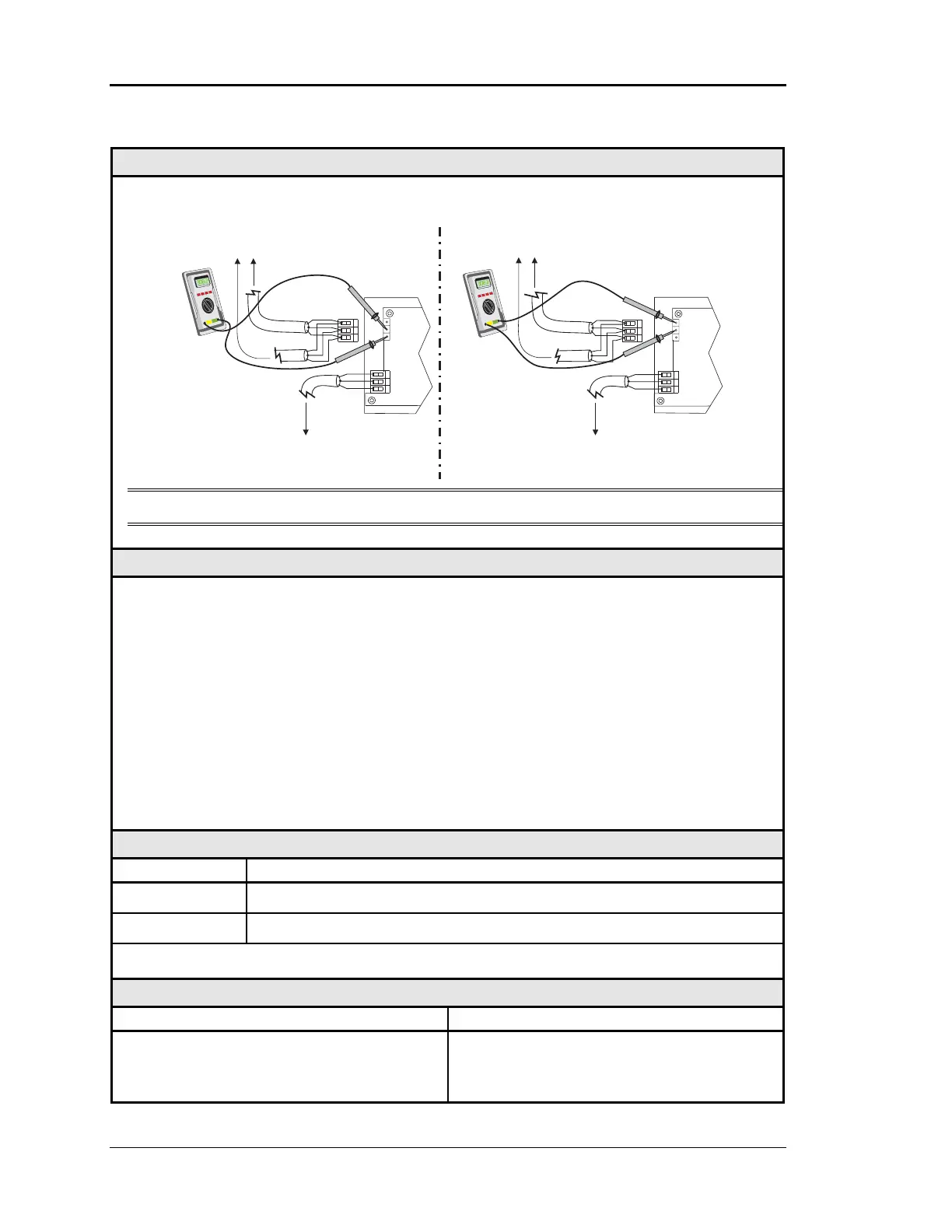
Checking the MiniLink Network Driver – CV-EX
Diagram
Meter Set To Read DC Volts
NETWORKNETWORK
LOOPLOOP
G
T
R
GT
R
+
-
+
-
+2.4 VDC
to
+2.5 VDC
R-to- G
T-to- G
NETWORK
LOOPLOOP
G
T
R
GT
R
+
-
+
-
+2.4 VDC
to
+2.5 VDC
To Other MiniLinks
Or CommLink
On The Network Loop
To Other MiniLinks
Or CommLink
On The Network Loop
MiniLink
MiniLink
To CV Controllers
And System Manager
On Local Loop
To CV Controllers
And System Manager
On Local Loop
Note: These tests assume that the MiniLink being checked is powered up
Overvie
This check is intended to determine if the Network Comm Driver chip on a MiniLink is
damaged.
Tip Before unplugging the Network loop from the MiniLink, observe the Network Loop
LED (located near the connector). It should periodically “flicker” as the CommLink
requests data from the MiniLink. The LED will also flicker when power to the
CommLink is cycled. If the LED is not flickering, the unit is not communicating with
the CommLink.
Damage typically occurs when the communications loop is exposed to excessive voltage, as
may occur during installation due to wiring errors. The driver chips are socketed on all
boards to facilitate servicing. It is unusual for driver chips to fail during normal operation.
Almost all failures occur as a result of wiring related problems.
Measurements
Network Loop Acceptable Range
T – SHLD 2.4 - 2.5 Volts DC
R – SHLD 2.4 - 2.5 Volts DC
Note Minor variances may not indicate a problem if both tests indicate similar values
Action
Condition Action
If voltages are too high or too low on either
side
The MiniLink has a damaged Network
Comm Driver chip. Replace the driver
chip. See Figure 4-9.