EasyManua.ls Logo

Waveshare Barcode Scanner Module User Manual

Default Icon
57 pages
To Next Page IconTo Next Page
Page #1 background imageLoading...
Page #1 background image
Barcode Scanner Module User Manual
1 / 57 Rev1.0 Date:180621
Barcode Scanner Module
User Manual
OVERVIEW
This is a small 1D/2D codes reader, by using the intelligent image recognition
algorithm, it will decode the barcode or 2D code on paper or screen, fast and
accurately.
Through the onboard USB and UART interface, it can be directly plugged into a
computer, or be easily integrated to kinds of devices due to its small form factor.
FEATURES
Easy to use, requires no knowledges of image recognition
Decodes various common 1D/2D codes such as Barcode, QR code etc.
Onboard micro USB and UART serial port, allows to connect with computers or
embedded devices
Configurable via scanning 'configuration code'
Onboard light source, works in the dark
Question and Answer IconNeed help?

Do you have a question about the Waveshare Barcode Scanner Module and is the answer not in the manual?

Waveshare Barcode Scanner Module Specifications

General IconGeneral
ModelBarcode Scanner Module
InterfaceUART
Supported Barcode TypesUPC/EAN, Code128, Code39, Code93, Codabar
Operating Temperature0°C to 50°C
Storage Temperature-20°C to 60°C
Scanning Distance30mm

Summary

OVERVIEW OF BARCODE SCANNER MODULE

KEY FEATURES

Lists key capabilities like easy use, decoding various codes, USB/UART interface, configuration via codes, and onboard light source.

TECHNICAL SPECIFICATIONS

SUPPORTED BARCODE TYPES

SCANNING INSTRUCTIONS

SCANNING AREA AND DISTANCE

Explains scanning distance and provides a diagram illustrating white light, red light, and FOV areas.

SCANNING ORIENTATION AND TECHNIQUES

SKEW ANGLE SCANNING

Explains how skew affects barcode scanning and its acceptable limits.

PITCH ANGLE SCANNING

Details pitch angle's effect on barcode scanning and optimal angles.

CONFIGURATION INSTRUCTIONS

HARDWARE CONNECTION METHODS

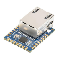
Describes connecting the module via USB or UART interfaces and pinouts (VCC, Tx, Rx, GND).

SETTING CODE FUNCTIONALITY

Explains that users can scan setting codes to configure the module, enabling/disabling this function.

SETTING CODE MANAGEMENT

ENABLE/DISABLE SETTING CODE FUNCTION

Provides QR codes to enable or disable the setting code function for configuration.

SETTING CODE OUTPUT CONTROL

Shows QR codes to control whether the output content of setting codes is displayed.

RESTORE FACTORY SETTING

USER DEFAULT SETTINGS MANAGEMENT

SAVE CURRENT SETTING AS USER DEFAULT

Allows saving the current configuration as a user default setting, overwriting previous defaults.

RESTORE USER DEFAULT SETTING

Restores the module's configuration to the saved user default setting.

UART COMMUNICATION SETUP

UART BAUD RATE CONFIGURATION

Lists QR codes to set various baud rates for UART communication.

USB COMMUNICATION MODES

USB PC KEYBOARD MODE

Explains how to set the module to keyboard input mode via USB.

USB VIRTUAL PORT MODE

Describes setting the module to USB virtual port mode.

SCANNING MODES

MANUAL SCANNING MODE

Explains the default scanning mode requiring a button press to scan.

SLEEP MODE CONFIGURATION

Details how to enable or disable the sleep function in manual mode for idle periods.

CONTINUOUS SCANNING MODE

CONTINUOUS MODE SCANNING TIME

Sets the maximum scanning time per scan attempt in continuous mode.

CONTINUOUS MODE NON-SCANNING INTERVAL

Sets the time interval between scanning behaviors.

SENSING SCANNING MODE

SENSING MODE SCANNING TIME

Sets the max scanning time for per scanning behavior in Sensing Mode.

SENSING MODE INTERVALS

Sets the interval between scanning and detecting in Sensing Mode.

SENSING MODE IMAGE STABILIZATION

Sets the time for stabilizing the image after detecting brightness changes in sensing mode.

COMMAND MODE OPERATION

COMMAND MODE SCANNING TIME

Sets the maximum scanning time for per scanning behavior in Command Mode.

LIGHTING AND TARGETING FEATURES

LED LIGHTING MODES

Describes the white LED for scanning and its three states: Standard, Keep lighting, No light.

TARGETING LIGHT MODES

Explains the targeting light beam for distance and angle, and its settable states.

OUTPUT INDICATION SETTINGS

BUZZER WARNING TONES

Describes setting the buzzer for active/passive operation and driving frequency.

BUZZER DRIVING FREQUENCY OPTIONS

Details setting the driving frequency of the passive buzzer (LF, MF, HF, Active).

BUZZER WORKING LEVEL OPTIONS

Allows setting the working level of the buzzer in active driving mode (High, Low).

SILENCE ALL WARNING TONES

Explains how to turn off all warning tones using a specific code.

SCANNED TONE SETTINGS

OPEN/CLOSE SCANNED TONE

Allows setting the buzzer behavior when a barcode is scanned successfully.

SCANNED TONE DURATION

Allows setting the duration of the warning tone, with a default of 60ms.

DECODING PROMPT FUNCTION

KEYBOARD SETTING OPTIONS

KEYBOARD LAYOUT SELECTION

Offers keyboard setting codes to match different country layouts (US, Czech, French, etc.).

IMAGE FLIP FUNCTIONALITY

NORMAL VS FLIPPED MODE SELECTION

Provides QR codes to switch between normal and flipped image modes.

MODULE VERSION INFORMATION

DATA EDITING FEATURES

PREFIX SETTING OPTIONS

Allows adding a definable string before the decoded data.

SUFFIX SETTING OPTIONS

Allows adding a definable string after the decoded data.

CODE ID MANAGEMENT

Allows using CODE ID to identify different barcode types.

RESTORING DEFAULT CODE ID

Restores all barcode information to their default CODE IDs.

CHANGING SPECIFIC CODE IDS

CODE ID LIST FOR MODIFICATION (PART 1)

CODE ID LIST FOR MODIFICATION (PART 2)

TERMINATOR SETTING OPTIONS

DATA SEGMENT INTERCEPTION

CHANGING START SEGMENT LENGTH

Explains how to change the length of the Start segment, up to 255 characters.

EXAMPLE: OUTPUT START SEGMENT DATA

Example of outputting only the first thirteen bytes as the Start segment.

EXAMPLE: OUTPUT END SEGMENT DATA

Example of outputting the last three bytes as the End segment.

EXAMPLE: OUTPUT CENTER SEGMENT DATA

Example of outputting the center four bytes as the Center segment.

RF INFORMATION CONFIGURATION

MODIFYING RF (READ FAIL) INFORMATION

Allows modification of RF (Read Fail) information, up to 15 characters.

BARCODE TYPE ENABLE/DISABLE CONTROLS

ALL TYPES ENABLE/DISABLE

Enables or disables all barcode types; only setting codes are scannable if all are disabled.

BARCODE ROTATION SETTINGS

Enables or disables the 360° rotation support, which can affect decoding speed.

360 DEGREE ROTATION ENABLE/DISABLE

EAN13 BARCODE ENABLE/DISABLE

EAN8 BARCODE ENABLE/DISABLE

UPCA BARCODE ENABLE/DISABLE

UPCE0 BARCODE ENABLE/DISABLE

UPCE1 BARCODE ENABLE/DISABLE

CODE128 BARCODE ENABLE/DISABLE

CODE 39 BARCODE ENABLE/DISABLE

CODE 93 BARCODE ENABLE/DISABLE

CODE BAR ENABLE/DISABLE AND SETTINGS

QR CODE ENABLE/DISABLE

INTERLEAVED 2 OF 5 ENABLE/DISABLE

INDUSTRIAL 25 ENABLE/DISABLE

MATRIX 2 OF 5 ENABLE/DISABLE

CODE11 ENABLE/DISABLE

MSI ENABLE/DISABLE

RSS ENABLE/DISABLE

RSS LIMITED/EXPANDED ENABLE/DISABLE

DM (DATA MATRIX) ENABLE/DISABLE

PDF417 ENABLE/DISABLE

APPENDIX A: DEFAULT SETTING TABLE

MODE SETTINGS SUMMARY

APPENDIX B: COMMON UART COMMANDS

APPENDIX C: CODE ID LIST

APPENDIX D: ASCII TABLE

APPENDIX F: SAVE AND REMOVE OPTIONS

Related product manuals