5
BUILT-IN SLEEVE GAS
LINE LOCATIONS
Side Burner Tolerances
A1
19
⁄32”
B8”
DIMENSIONS
+
1
⁄16
-
1
⁄16
+
1
⁄16
-
1
⁄16
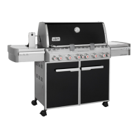
BUILT-IN SLEEVE GAS LINE
LOCATIONS
The dimensions shown indicate the location of the gas
line inlet flange in the sleeve. The support members of
the built-in structure must not impede passage of the
gas lines.
Area should be kept clear of sharp, jagged, or extremely
abrasive surfaces to avoid possible damage to gas supply
lines. Exercise caution when pulling gas lines through
built-in structure.
Note: Leave an access in the structure for gas supply
and regulator service.
Figure 6
B
A
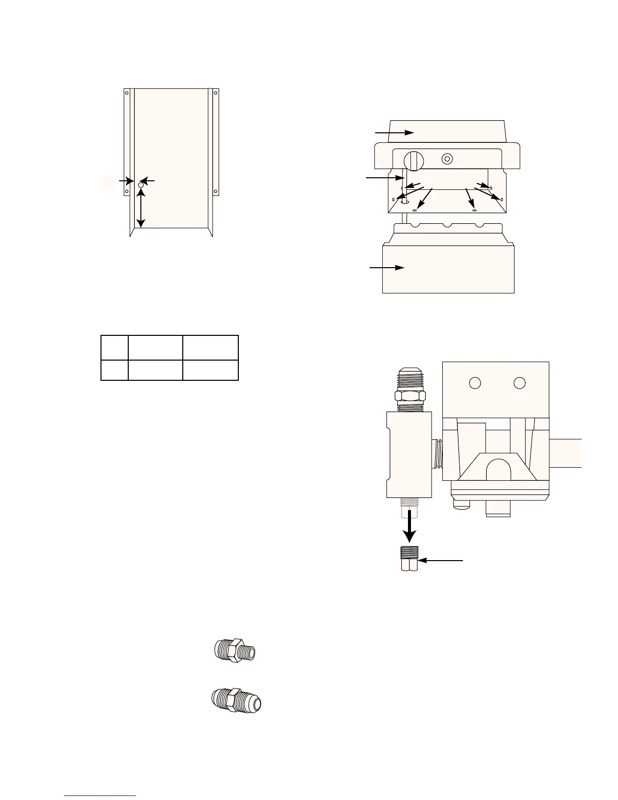
REMOVE PACKAGED
CONTENTS
1/8 NPT x 3/8 inch SAE
flare fitting
3/8 inch SAE flare fitting x
3/8 inch SAE flare fitting union
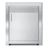
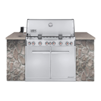
SIDE BURNER ASSEMBLY
The side burner and side burner sleeve are factory
assembled. To secure into the cutout, remove the front
panel. Secure the sleeve at the holes in the sleeve.
Figure 7.
Figure 7
Secure here
hose
lid
front panel
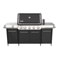
Remove the the brass plug from the regulator assembly.
Figure 8.
Brass plug
View from top
Figure 8
 Loading...