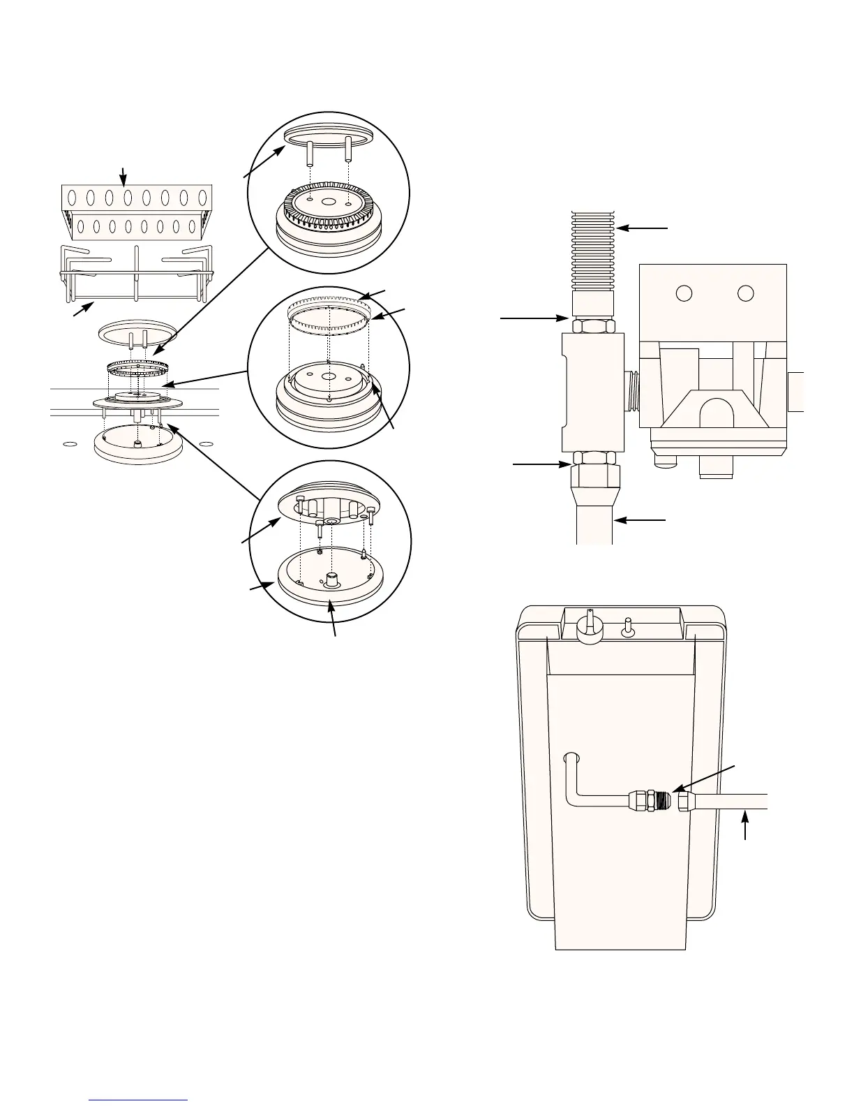
7
Figure 12
(a)
(c)
(b)
Burner cap
Burner ring
Burner head
Burner base
Windshield
Grate
Burner orifice
Slot
Slug
Check that the side burner is properly assembled.
WARNING: Set the burner ring onto the burner head.
Rotate the burner ring until the four lugs on the
burner ring are seated in the four slots on the
burner head. Figure 12 (b).
SIDE BURNER ASSEMBLY LEAK CHECK GAS
CONNECTIONS
Leak check connections:
a) Corrugated hose to regulator assembly. Figure 13 (a).
b) Regulated gas supply line to side burner. Figure 13 (b).
c) Side burner gas line to regulated gas supply. Figure 14.
a)
c)
b)
Figure 13
Figure 14
Corrugated hose
To side burner
Gas supply
from regulator
 Loading...