5
DETAILED PARAMETER DESCRIPTION
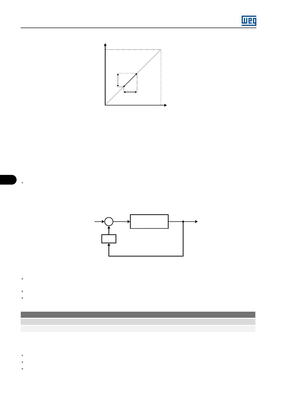
N
nom
V
nom
(Motor
load
function)
ΔV
ΔF
Output voltage
Speed
Figure 5.13: V/F curve with slip compensation
P0138 adjustment procedure:
1. Drive motor with no load, at approximately half the use speed range.
2. Measure the motor or equipment speed.
3. Apply rated load to the equipment.
4. Increment parameter P0138 until the speed reaches the value with no load.
Values P0138 < 0.0 are used in special applications to reduce the output speed as a function of the increase
in the motor current. Ex.: load distribution on motors driven in parallel.
Vector Mode (Droop Control):
TorqueTotal reference
Speed
regulator
P0138
+
+
Figure 5.14: Block diagram P0138 (vector)
In the vector mode (encoder or sensorless) parameter P0138 has the function described in Figure 5.13 on
page 5-20.
A value proportional to the motor load is added to the total speed reference is added.
This parameter is used in the multimotor application.
P0139 - Output current filter
Adjustable range: 0.0 to 16.0 s Factory setting: 0.2 s
Acesso: Menu → Configurations → Control
Description:
It sets the time constant of the active current filter.
It sets the response time of the slip compensation and automatic torque boost.
See Figure 5.10 on page 5-19 and Figure 5.12 on page 5-19 .
MVW3000 | 5-20