4
HMI OPERATION
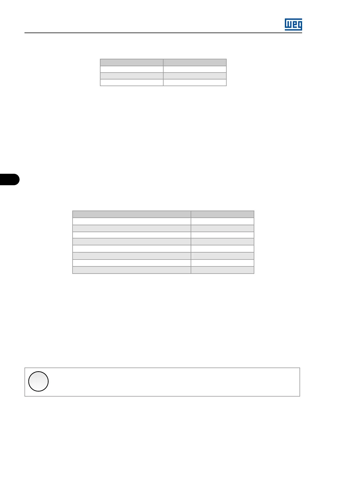
Table 4.3: HMI commands selection
Option Description
000 Inactive
001 Local HMI
002 Remote HMI
In [Local HMI] and [Remote HMI] modes, the parameters P0220...P0228 are programmed according to the exam-
ples of configurations previously described.
4.4.3 Configuring the Monitoring Mode Read-Only Parameters
In the monitoring mode, the HMI is able to present from 1 to 6 read-only parameters simultaneously. The param-
eters P0500...P0505 select which read-only parameters will be presented Refer to Table 4.4 on page 4-8 in order
to identify the possible programmable parameters.
The number of read-only parameters presented depends on how many parameters P0500...P0505 are pro-
grammed different from ‘0 = Inactive’.
Table 4.4: Possible read-only parameters in the monitoring mode
Description
Full Scale
Motor speed reference
P0208
Motor speed
P0208
Motor Current
P0295
Motor Frequency
P0403
Output voltage
P0296
Motor Torque
(P0295/P0401) * 100 %
Inverter output power
1,732 * (P0295 * P0296)
Value of process variable (PID)
100 %
4.4.4 Configuring the On-line Graphic
In the on-line graphic visualization mode, the user is able to program up to two read-only parameters (refer to P0512)
for real time graphic monitoring on the HMI. This programming is done in a similar form to the programming of the
monitoring mode (Menu → Configurations → HMI → Graphic). The variable updating (sampling) is slow, and the
objective is of monitoring in real time the inverter situation. Data is not saved in any memory device, i.e., it is only
for real time monitoring.
The graphic function is accessed through the [Graphic] softkey, from the parameter monitoring mode.
✓
NOTE!
For the [Graphic] softkey to be available, it is necessary that at least one read-only parameter be
programmed for Graphic (Menu → Configurations → HMI → Graphic).
MVW3000 | 4-8