Device description
2903400000/00/09.202210
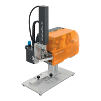
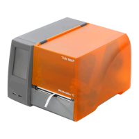
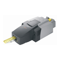
3.3 Applicator
1
2
3
4
5
6
7
8
9
10
4
8910
11 12 13 14
15
16
17
3
Image 3.6 Front and rear
1 Spiral hose
2 Energy chain
3 Compressed-air maintenance unit
4 Knurled screw to fasten the applicator on the printer
5 Main cylinder
6 Cylinder assembly cover
7 Mini slide
8 Stamp
9 Blowpipe for support air
10 Laser pointer
11 Interface to the printer
12 Locking pins
13 Coupling for the compressed-air connection
14 Shut-off valve
15 Pressure gauge for the working pressure
16 Throttle valve for support air
17 Throttle valve for vacuum