14
83055116 • 1/2016-05
Installation and Operating Instructions
G
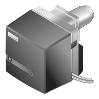
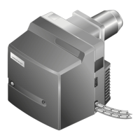
as burner WG20.../1-C ZM-LN (W-FM 25)
3 Technical description
3
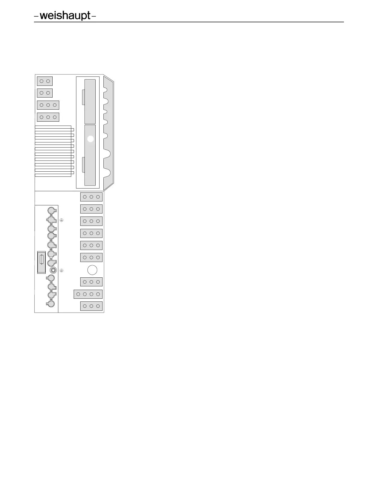
.3.5 Inputs and outputs
See the wiring diagram - Ch. 3.3.4
TWI TWI Interface (VisionBox)
P Not used
NA Speed signal (Namur)
VSD Variable speed drive
AM Operating panel
L/A Air damper stepping motor
G Gas butterfly valve stepping motor
1 Slot for analogue module EM3/3 or Fieldbus module EM3/2
1 External valve LPG (optional)
3C Burner motor for continuous running blower
3N Burner motor for normal blower operation
4 Ignition unit
5 Double gas valves
6 Not used
7 Bridging plug No. 7
8 Gas meter (impulse generator)
11 Air pressure switch
12 Gas valves Proof of Closure switches (POC)
13 Ionization electrode
14 Low gas pressure switch
15 High gas pressure switch
X6 7-pole connection plug (power supply, On/Off control, status signals)
X7 4-pole connection plug (2-stage or modulating control)
F7 Internal unit fuse, 6.3 AT
-weishaupt-
13
3
N
7
3
C
4
1
6
5
14
L
N
T1
T2
S3
B4
B5
T6
T7
T8
G L/A AM FU NA P
TWI
8
11
15
12
X6
X7
F7
1
 Loading...