12
3 Technical description
3
.3.4 Program sequence
The burner operating phases are shown on the display, as following:
Phase Function
TEST After the power supply is switched on, the combustion manager performs a self-test.
G L At call for heat, the air and gas stepping motors drive to the reference position.
1 The combustion manager monitors for extraneous light or flame.
2 The air damper stepping motor drives to pre-purge (operating point P9 ). The gas butterfly stepping
motor drives to ignition position (operating point P0 ).
3 The pre-purge is started. The air pressure switch is checked and must be closed.
4 Pre-purge. The remaining pre-purge time is displayed.
5 The air damper stepping motor drives to ignition position (operating point P0 ).
6 Gas valve V1 opens. The low gas pressure switch is checked and must be closed. Ignition spark starts.
7 Gas valve V2 opens. The gas is released. The safety time begins. The display shows the symbol
8 Flame stabilization. The high gas pressure switch is checked and must be closed.
9 The air damper and gas butterfly valve stepping motors drive to low fire.
10 The burner is in operation. Ready for modulation.
11...14 Valves proving sequence is activated - optional, for special applications.
15 Following the post-purge, the burner motor is turned off. The air damper and gas butterfly valve are closed.
OFF Stand-by, no call for heat.
Installation and Operating Instructions
G
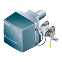
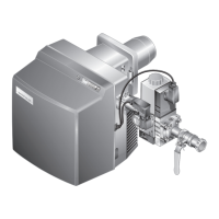
as burner WG20.../1-C ZM-LN (W-FM 25)
83055116 • 1/2016-05
 Loading...
