13
83055116 • 1/2016-05
Installation and Operating Instructions
G
as burner WG20.../1-C ZM-LN (W-FM 25)
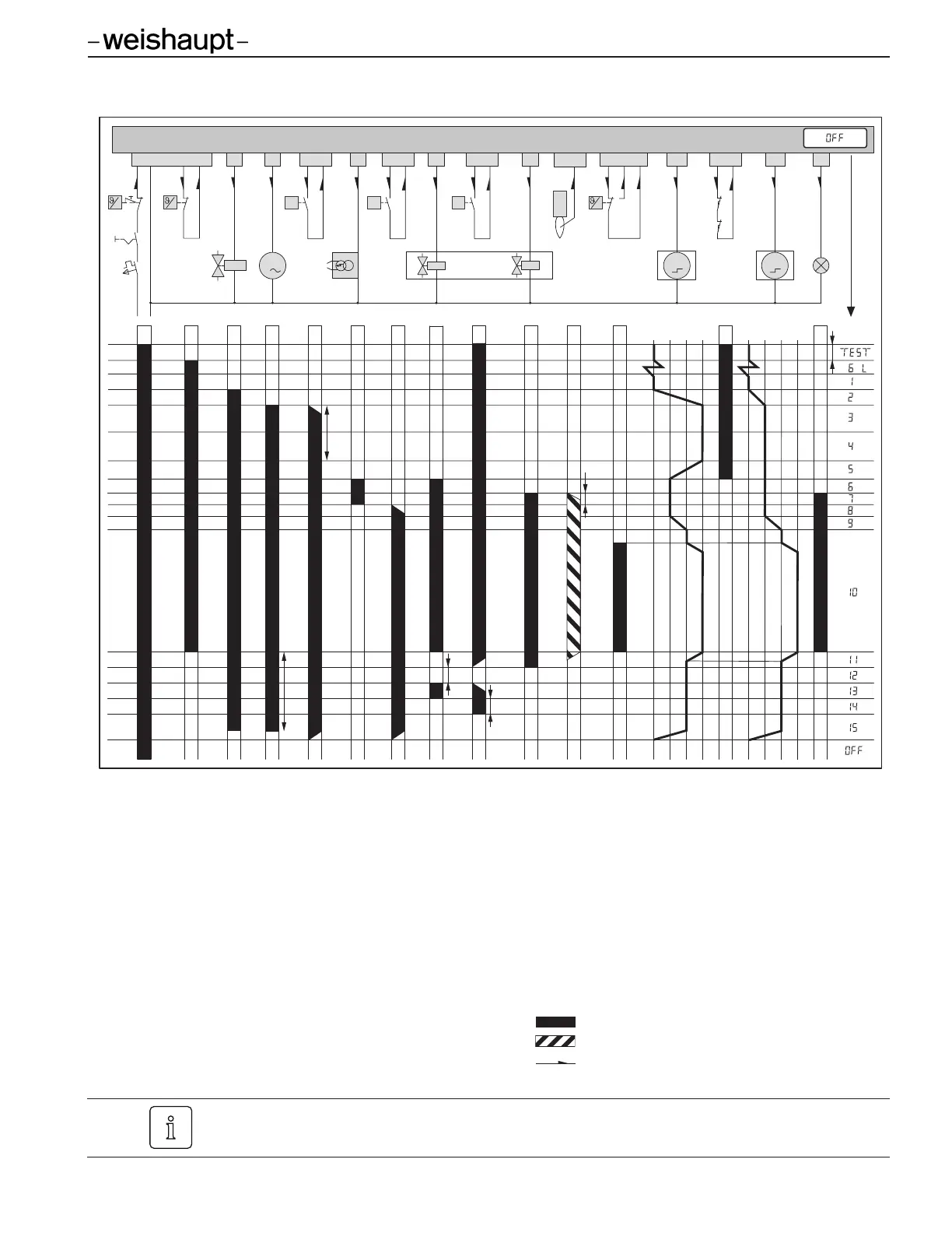
3 Technical description
B1 Ionization electrode 1 CLOSED position
B10 Air pressure switch 2 Ignition position
B15 Temperature/pressure operating ctrl. (On/Off) 3 Low fire
B16 Temperature/pressure 2-stage or modulating ctrl. 4 High fire
B31 Low gas pressure switch 5 Operating phase
B33 High gas pressure switch T
I
Initialization time (test): 3 sec
F2 Temperature/pressure safety limit T
N
Post-purge time: 2 sec
K32 Double gas valve T
P1
1. Test phase: 8 sec (proving V1 - optional)
K33 External valve LPG (optional) T
P2
2. Test phase: 16 sec (proving V2 - optional)
M1 Burner motor T
V
Pre-purge time: 60 sec
M20 Air damper stepping motor T
S
Safety time: 4 sec
M38 Gas butterfly valve stepping motor The device is energized
P11 Burner status light (optional) Flame signal is present
T1 Ignition unit Current path
S32 Proof of Closure switch V2 (POC2) S34 Proof of Closure switch V1 (POC1)
Operating phases 11 to 14 are only applicable if the valve proving system (VPS) is
activated.
T
V
T
S
T
N
T
P1
T
P2
B4
P11
W-FM 25
K33
1
P
B16
T
6T8T7
B10
P
11
B31
P
14
B33
P
15
5
K32
5
21
M
1
M1
3
T1
4
P
P
B15
L
T1
T
2
F2
N
L
N
M
M20
1234
M
M38
1234 5
T
I
L
/AG
B
1
13
S34
12
S32

 Loading...