Rotary indexing ring TR
Controller
10 Controller
10.1 Basic information on control
WARNING
LOSS OF CONTROL
Failure to follow these instructions can result in death, serious injury, and
equipment damage.
■
Consider all potential failure modes of all control paths in your control concept.
■
Implement means and measures for all critical functions to achieve a safe state if
a control path fails (for example, emergency stop, overtravel of positions, power
outage, and restart).
■
Implement separate or redundant control paths for all critical functions.
■
If the control system of the machine comprises communication links, consider
the consequences of unanticipated transmission delays or failures of the link and
implement appropriate measures.
■
Subject each machine in which the product described in these mounting
instructions is used to a comprehensive and thorough commissioning test before
operating the machine.
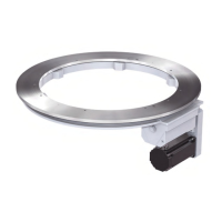
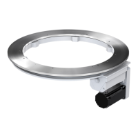
The output flange can be operated with the following directions of movement: left, right, or alternating.
A movement of the output flange is started by sending a start signal to the motor and applying the
holding brake voltage. This releases the holding brake and the motor accelerates.
To stop the movement of the output flange, a stop signal is sent to the motor and the motor decelerates
to a standstill. After the motor has decelerated to a standstill, the supply voltage to the holding brake is
removed. This applies the holding brake. The output flange is at one of the possible positions.
The holding brake is not a service brake, i.e. it is not used to decelerate the load to a standstill, but to
maintain the load at a standstill.
If no external controller is used, the gear determines the cycles.
The cycle time is fixed (determined via the gear) or it can be adjusted via the controller.
A signal "P" (output flange in position) can be generated via the inductive sensor. This signal can
be used to control the motor and the holding brake; the signal can also be used as a start signal for
processing units.
42 / 79
Mounting instructions_062019_4.0_en