Rotary indexing ring TR
Maintenance
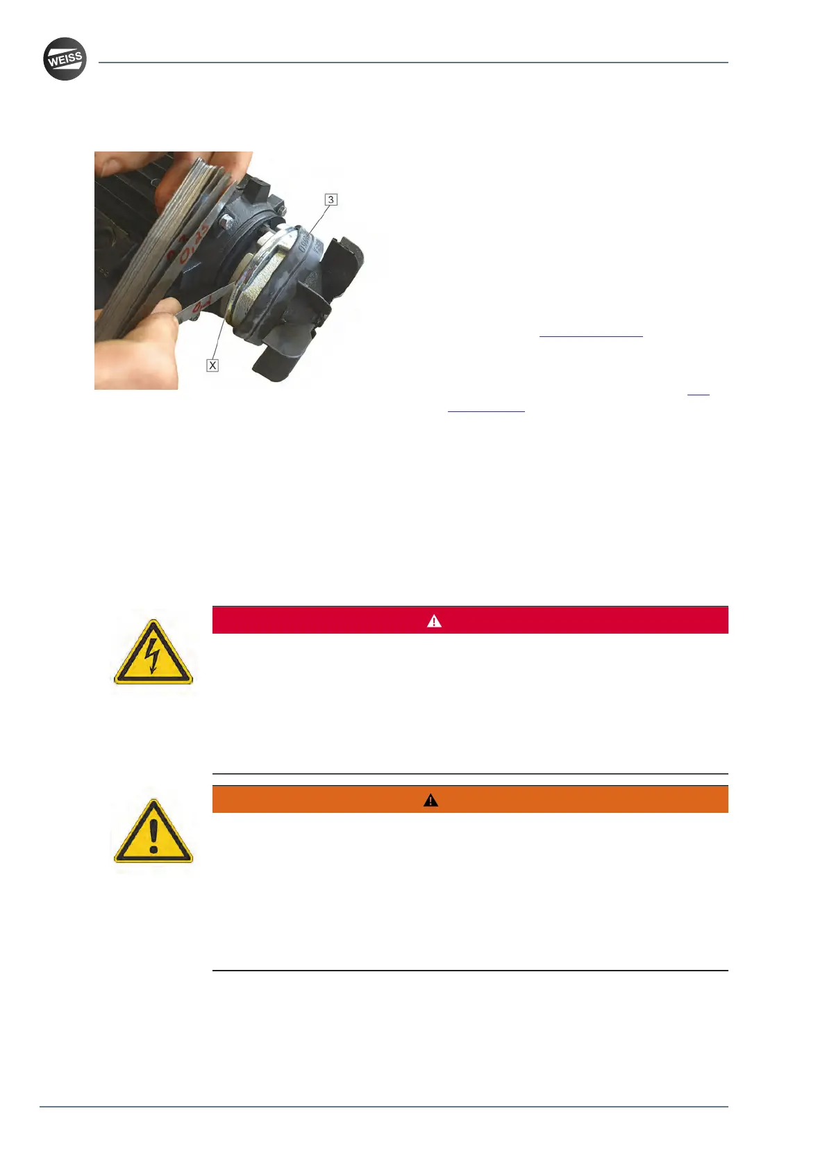
2. Pull the protective rubber [3] towards the fan
wheel.
3. Blow out abrasion material with compressed
air.
4. Measure the air gap [X] with a feeler gauge.
The size of the air gap must not exceed
0.2 mm.
P
If the size of the air gap exceeds the
permissible tolerance value, the air gap must
be readjusted, see chapter 15.7.
P
If it is not possible to adjust the air gap to
a size of 0.2 mm, the brake lining or the
entire holding brake must be replaced, see
chapter 15.8.
5. Pull the protective rubber [3] back into its
initial position.
6. Screw the fan cap [2] to the motor.
7. Remove all tools and equipment.
8. Perform a test run.
15.7 Readjusting the air gap of the holding brake
DANGER
ELECTRIC SHOCK CAUSED BY LIVE PARTS
Failure to follow these instructions will result in death or serious injury.
■
Disconnect the mains supply voltage before performing the work and ensure that
it cannot be switched on.
■
Verify that no hazards can be caused by electrically conductive objects.
■
Verify that all cables for the power supply are disconnected from power.
WARNING
UNANTICIPATED MOVEMENT OF THE ROTARY RING/THE ROTARY RING
The gear is not self-locking. When the drive and the output flange/rotary ring are
decoupled, the output flange/rotary ring can move.
Failure to follow these instructions can result in death, serious injury, and
equipment damage.
■
Block or safeguard the output flange/rotary ring in such a way that a movement
of the output flange/rotary ring is safely prevented before releasing the holding
brake or decoupling the drive and the output flange/rotary ring.
64 / 79
Mounting instructions_062019_4.0_en