32 WILO SE 11/2016 Ed.01 DIN A5
English PRODUCT DESCRIPTION
Guide pipe sizes and material versions
Type Number Material
Size* in mm
(*OuterØxwallthickness)
DN 50/2RK 2x A2 26.9x2
DN 65/1RK 1x A2 26.9x2
DN 65/2RK 2x A2 26.9x2
DN 80/2RK 2x A2 42.4x2
DN 100/2RK 2x A2 42.4x2
DN 100S/2RK 2x A2 42.4x2
DN 150L/2RK 2x A2 42.4x2
DN 150S/2RK 2x St 33 60.3x3.65
DN 200/2R 2x A2 42.4x2
DN 250/2R 2x A2 42.4x2
DN 250S/2RK
2x St 33
60.3x3.65
Suspension units may not be used without guide pipes. Otherwise, the pump will slip
base to leak and the pump may be damaged. To prevent this, the use of guide pipes
is mandatory.
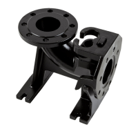
4.3. Position
Together, the coupling base, guide pipe bracket and guide pipes form the suspension
unit. This is installed in the operating area and connected to the discharge-side pipe
system.
The connected pipe system must be self-supporting. This means it must not be
supported by the coupling base.
Thecouplingangeismountedonthedischargeangeofthepump.Ithasguideclaws
to guide it along the guide pipe so that the pump can be connected to the coupling
base.
Thecouplingangeisautomaticallyconnectedtothecouplingbasebytheweightof
the pump.
Asealingringisinsertedinthecouplingangetoensurethatthereisnoleakagebe-
tweenthecouplingangeandthecouplingbase.Thesealingringispushedagainstthe
coupling base during operation, thus sealing the connection.
To ensure unimpaired operation, the suspension unit must be installed vertically
 Loading...