INSTALLATION English
Installation and operating instructions Wilo EHV G2 - DN250 37
1. Mark out the holes on the building material.
2. Drill the holes according to the instructions.
3. Thoroughly clean the holes.
4. Insertthexanchorinthehole.
5. Knock and fasten the bolt into the wall with two or three sharp hammer blows.
6. Oncealltheanchorshavebeentted,cleananyimpuritiessuchasdirt,adhesiveresin
ordrillingdustfromthesurface.Thecomponenttobeattachedmustbermlyttedto
the base and may not be in any way loose.
7. Boltthecomponenttothefoundationandtightenitwiththespeciedtorque.
Thenutmustbecoatedwithlockingadhesive.
5.3. Assembling the suspension unit
5.3.1. Guide pipe bracket
The guide pipe bracket is attached to the pit entrance using bolts and masonry anchors.
When positioning it, make sure the coupling base is installed vertically under the guide
pipe bracket.
1. Place the guide pipe bracket on the pit entrance and mark out the drill holes.
2. Drill the holes and thoroughly clean them.
3. Fasten the anchors and mount the guide pipe bracket on the pit entrance using the
bolts supplied. Tighten the bolts only gently.
Stainless steel guide pipe bracket
The stainless steel version consists of several individual components which are supplied
assembled.
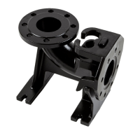
Fig. 2.: Assembling the stainless steel guide pipe holder
1 Base plate 4 Washer
2 Clamping screw 5 Guide pipe
3 Rubber buffer
This bracket is characterized by the additional fastening of the guide pipe with a rubber
buffer.
When the clamping screw is tightened, the washer is pulled up, compressing the rubber
buffer. This additionally fastens the guide pipe.
5.3.2. Coupling base
Thecouplingbaseisinstalledverticallybelowtheguidepipebracketonthepitoor
usinganchorboltsorxanchors.Makesurethedischargepipesystemisself-support-
 Loading...