INSTALLATION English
Installation and operating instructions Wilo EHV G2 - DN250 33
4.4. Type code
Example:DN150L/2RK
• DN = discharge port connection type
• DN=angeconnection
• R = threaded connection
• 150 = discharge port
• L = design*
• Nospecication=standarddesign
• L = lightweight design
• S = heavyweight design
• 2R = number of guide pipes
• K = coupling base design
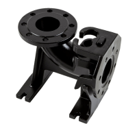
• K = with elbow
• Nospecication=withoutelbow;i.e.thedischargeportofthesuspensionunitis
horizontal.Toconnectaverticaldischargepipe,a90°pipeelbowisrequired.
4.5. Scope of delivery
• Coupling base
• Couplingange
• Guide pipe bracket for fastening in pit
• Fastening material
4.5.1. Material to be provided by the customer
• Guide pipe(s)
• 90°pipeelbowforsuspensionunitswithoutelbow
5. Installation
In order to prevent damage to the product or serious injury during installation,
thefollowingpointsmustbeobserved:
• Installation work – assembly and installation of the machine – may only be carried
outbyqualiedpersons.Thesafetyinstructionsmustbefollowedatalltimes.
• The machine must be inspected for transport damage before carrying out any installa-
tion work.
• The operating area must be clean, with coarse solid particles removed, dry, frost-free
and, if necessary, decontaminated.
• Wear appropriate protective clothing and equipment.
• A second person must be present for safety reasons when working in pits and reservoirs.
Ifthereisariskofpoisonousorasphyxiatinggasesforming,thenecessaryprecautions
must be taken!

 Loading...