Chapter 2: Getting Started
EN-24
The following devices are designed to be integrated with the 3rd party sensor
once required. Please refer to "Chapter 6: Appendix" on page 107. for more
details.
2.4.9 Analog Input (AI) Transducer
a. Power on the device.
b. Connect the wiring pin of 3rd party device by 4~20mA signal.
c. The Pin functions are as below:
Wire 1- (Red) DC 5~12V Power Input
Wire 2- (Black) Common & Negative 4-20mA Signal Input
Wire 3- (Yellow) Positive 4-20mA Signal Input
Wire 4- (Green) Reserved
Wire 5- (White) Reserved
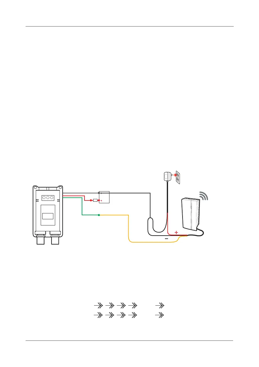
d. To connect the GTF200-FL Gas detector as example, please see the
following diagram:
e. Mount the bracket on the wall.
f. When configuring the detective range, the high range value is 20mA and the
low range value is 4mA (4~20mA). The threshold value will be set based on
percentage. (for example: when 20mA setting as 50, 4mA setting as 10; if
the threshold value setting as 40, that means the device will be triggered
while the current value over 16mA.)
(1)Signal current: 4mA 16mA 20mA
(2)Setting value: 10 40 50
Black
AI Transducer
F
DC POWER SUPPLY
24-30 VDC
(for instrument)
Legend and Description
B: Negative wiring of detector
R: Positive wiring of detector
G: Analog wiring of detector
F: Fuse
4-20mA Current
B
R
G
Yellow
Red
DC12v
Adapter