20
3062547_201507
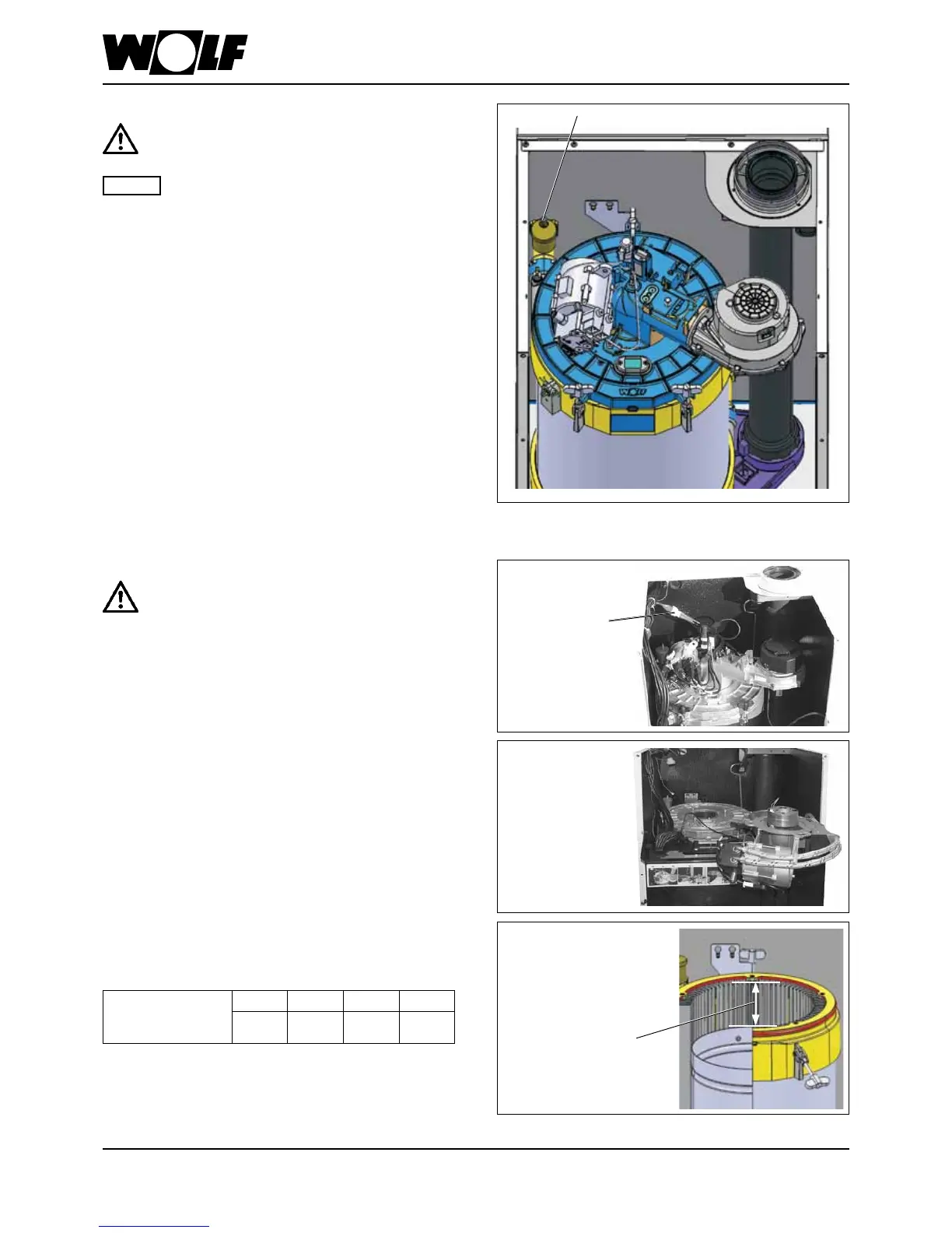
The displacement device may have slipped during
transport.
To ensure perfect combustion, check the
displacement device is correctly positioned before
commissioning the appliance.
- Unplug the central connector.
- Loosen the three 6 mm Allen screws on the burner ange
(do not unscrew them completely).
- Rotate the burner unit approx. 1 cm to the right
(clockwise).
- Lift the burner unit upwards out of the combustion
chamber lid and hang in place in the maintenance
position, as shown in the gure.
- Undo the wing screws on the combustion chamber lid.
- Lift off the combustion chamber lid and place to one side.
- Measure the distance between the upper edge of the top
displacement device and the upper end of the ridged prole,
then compare with the table below.
Displacement
device distance to
ridged prole (mm)
COB-15 COB-20 COB-29 COB-40
98-103 98-103 123-128 123-125
- Assembly is carried out in reverse order.
Fill the system and vent it properly to ensure
perfect boiler function.
Beforeconnectingtheboiler,ushtheheating
systemtoremoveresiduessuchaswelding
pearls,hemp,putty,etc.fromthepipework.
- Open the cap on the vent in the boiler by one revolution.
- Open all radiator valves.
- Fill the system via the return line at 2 bar (1.5 to 2.5 bar).
- With the entire heating system and boiler in a cold
condition, ll slowly via the inspection/ll & drain valve at
the return until 2 bar pressure is indicated.
- Check the entire system for water leaks.
- Start the boiler, set the heating water temperature to
position "2" (pump running, illuminated signal ring as
status indicator constantly green).
- Vent the pump; for this, briey open and then retighten the
air vent screw.
- Vent the heating circuit completely, switching the boiler
ON for 5 seconds and OFF for 5 seconds at the ON/OFF
switch, ve times in succession.
- When the system pressure drops below 1.5 bar, top up the
water.
NB
Air vent valve
Fillingtheheatingsystem
15.Fillingtheheatingsystem
Diagram: Venting the COB
Checkingthepositionofthedisplacementdevice
Diagram: View of COB displacement device
Displacement device
distance
Unplug the
central connector
Burner in the
maintenance position