37
3062547_201507
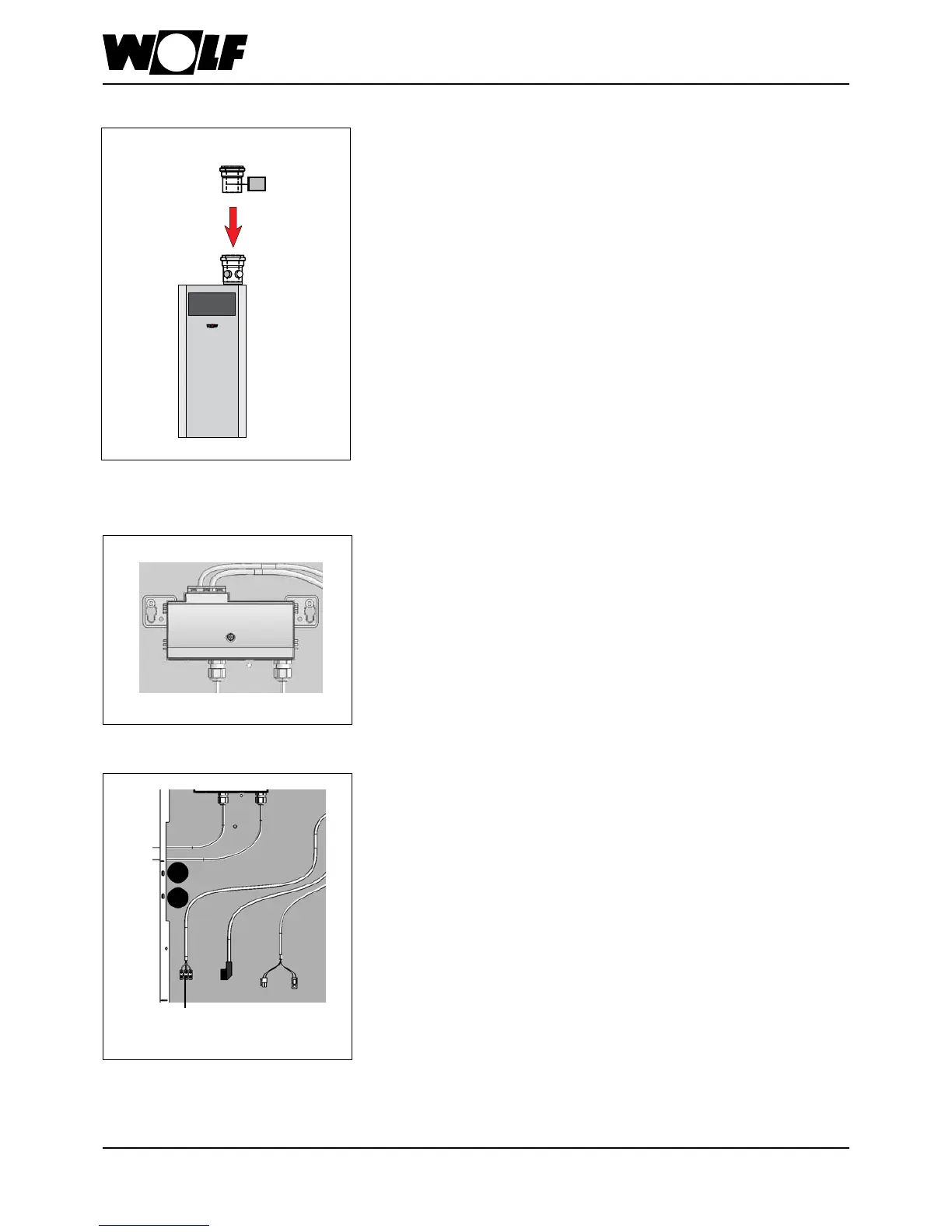
24. Cascade operation
Flue gas damper installation
- Push ue gas damper as far as it will go onto connection
adaptor (with test nipple) on the boiler.
- Push the ue as far as it will go onto the ue gas damper.
- Correctly route the limit switch cable and motor cable from
the ue gas damper to the terminal box and to the cable
(programmable output A1).
In the delivered condition, the terminal box is tted to the
back panel of the boiler.
If required, the terminal box can be mounted on the wall to
the right or left of the boiler, or above it.
The control, regulating and safety equipment are fully wired
and tested.
Installation information regarding electrical connection of
inputE1andoutputA1fortheuegasdamper
- Isolate the system from the power supply before opening.
- Unclip the terminal box from the holder.
- Open the terminal box.
- Insert the strain relief into the holes provided.
- Strip approx. 70 mm off the power cable from the limit switch.
- Push the cable through the strain relief and secure the strain
relief.
- Connect the wires from the limit switch to input E1
(see chapter 25 "Wiring diagram cascade operation").
- Connect motor cable from the ue gas damper via an on-
site junction box with programmable output A1
(see chapter 25 "Wiring diagram cascade operation").
- Fit the cover.
Proceed with chapter 26 "Flue gas damper tightness test"
and "Commissioning".
Terminal box
Flue gas damper installation
Flue gas damper
COB
Programmable
output A1
(230 VAC; 200 VA)
COB back view
Flue gas damper installation
information
Electrical connection installation
information