38
3062547_201507
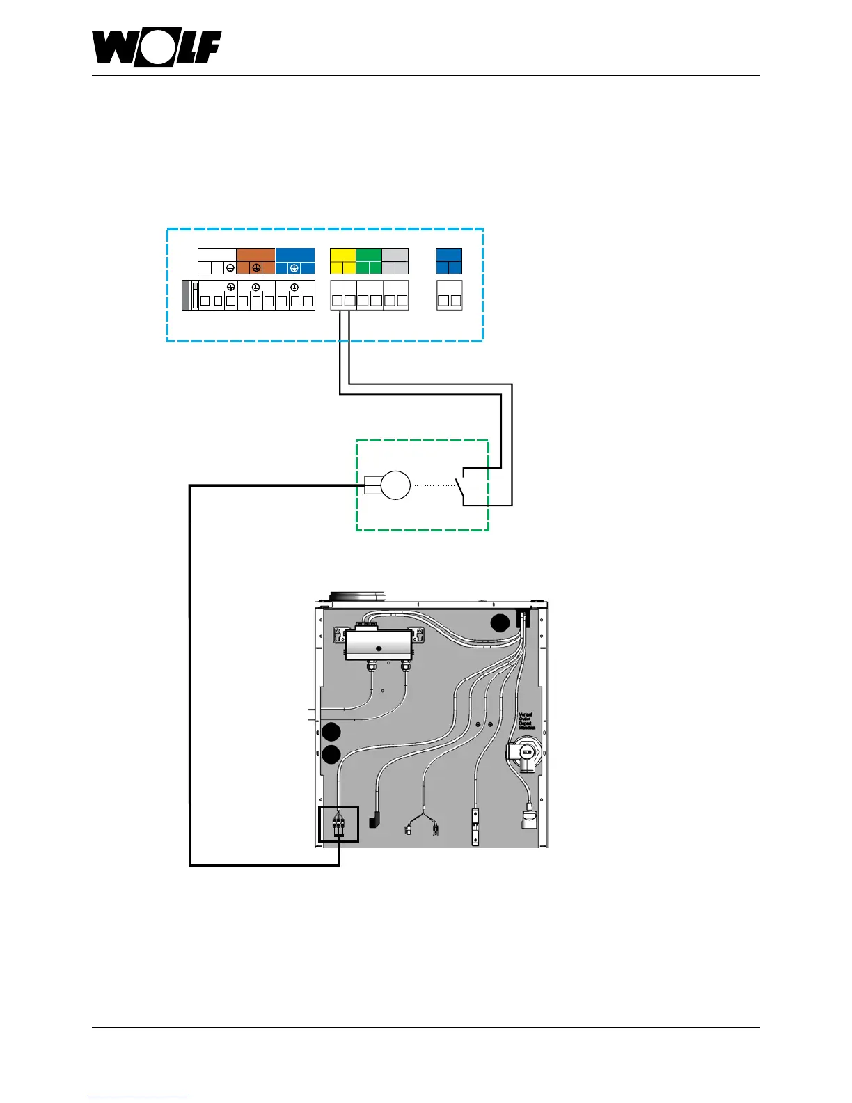
25. Cascade operation
Flue gas damper installation / wiring diagram
M
230 V~
Netz
KKP
LP
N
N
N
L1
L1
L1
L1
L1
L1
N
N
N
AF SF
E1
eBUS
+
-
1 1
2 2
a
b
12 12 12
12
COB terminal box
Flue gas damper with
servomotor
Limit switch
COB-15/20/29/40
Programmable output A1
(230VAC; 200VA)
NB:
Flue gas damper limit switch
must be zero volt. Otherwise
the COB control unit will be
destroyed.
Note:
Contractor parameter HG13
(input E1) must be set to 5 and
HG14 (output A1) must be set
to 7.
Power supply (230 VAC; 200 VA)
Flue gas damper wiring diagram
Junction box
on site