32
3062547_201507
SettingtheeBUSaddressfor
cascade mode
(seeinstallationinstructionsfor
KMmodule)
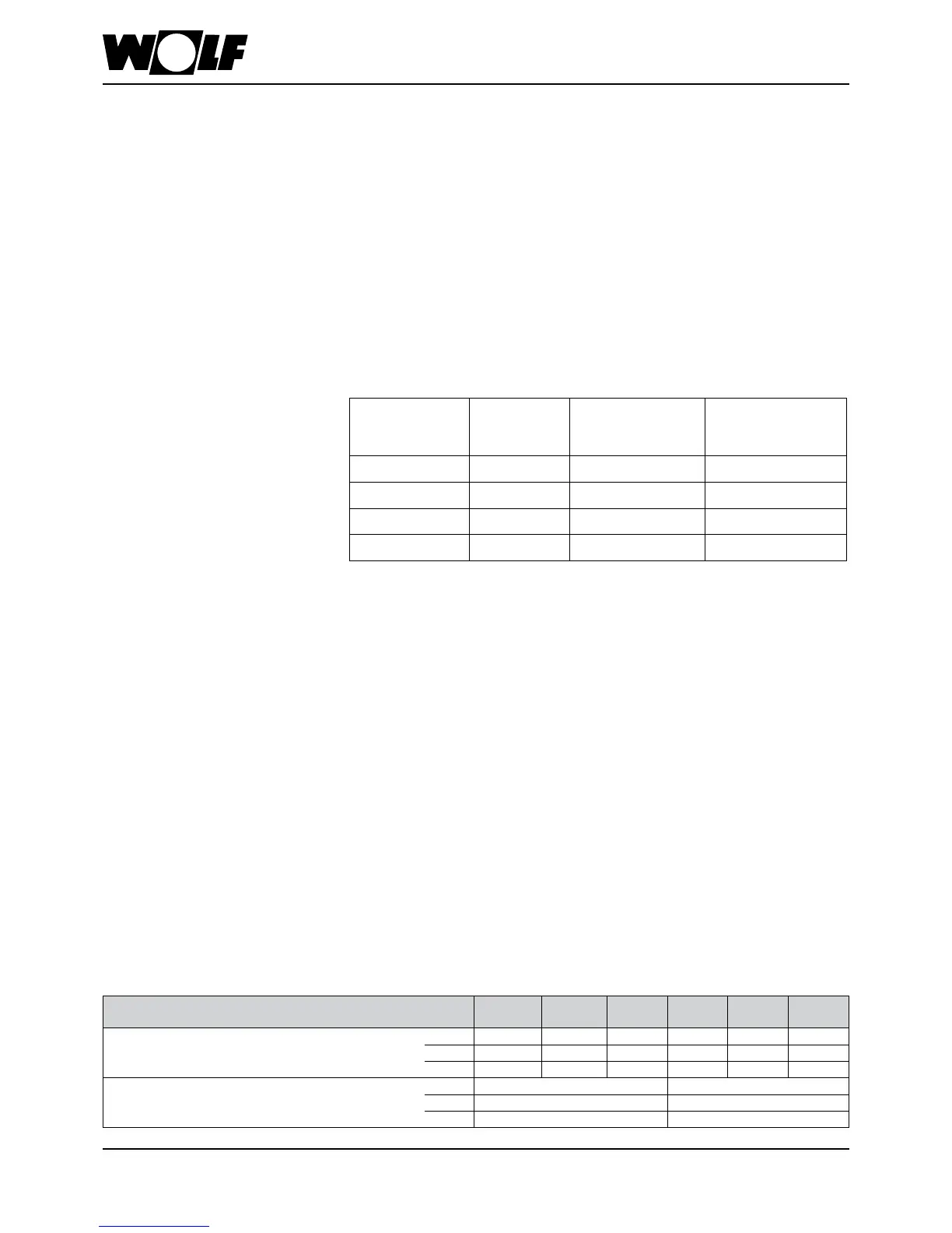
The eBUS address is set by pressing the reset button for at least 5 seconds after
the appliance has been switched on. After 5 seconds, the corresponding ashing
code appears (in accordance with the table) at the illuminated signal ring. Select the
corresponding eBUS address with the DHW temperature rotary selector. Your selection
of the required eBUS address is saved by releasing the reset button. No address can
be allocated more than once.
20. Cascade operation
Control/specication/notes
Cascadetype
2 x
COB-29
3 x
COB-29
4 x
COB-29
2 x
COB-40
3 x
COB-40
4 x
COB-40
Rated output at 80/60 °C
kW 56.4 84.6 112.8 76.0 114.0 152.0
Rated output at 50/30 °C kW 59.2 88.8 118.4 80.0 120.0 160.0
Rated heat input
kW 58.0 87.0 116.0 77.6 116.4 155.2
Lowest output at 80/60 °C Stage 1
kW 18.5 25.3
Lowest output at 50/30 °C Stage 1 kW 19.6 26.8
Lowest output
kW 19.0 26.0
Specication
Heating circuit
To ensure the heating water ow rate through every condensing boiler is as even as
possible, the following connection types are recommended:
1. For precise hydraulic balancing, a line regulating valve can be tted in the supply
line to every appliance.
2. Design the ow and return lines with the same length for the ow and return according
to the Tichelmann system, to ensure the pressure drop in every line is equally high.
These oil condensing boilers have control PCBs with functions that are optimally
matched to the digital controller type KM for cascade control. Up to four COB-29
or COB-40 oil condensing boilers (with the same output) with an output range of
18.5 kW to 112.8 kW (cascade COB-29) or 25.3 kW to 152.0 kW (cascade COB-40)
can be linked together to form a single cascade. Subject to load, this digital cascade
controller KM can control the header ow, a mixer circuit and a DHW cylinder circuit.
The digital controller type MM from the WOLF range of control accessories can be
connected to regulate an additional mixer circuit and radiator circuit. Furthermore, a
BM can be used in each case as a remote control.
For a detailed description, see also the installation instructions for the individual modules.
General
Low loss header
It must not be possible for the on-site heating circuit pumps or primary pumps to inuence
the function of the condensing boilers. A low loss header should therefore be installed
upstream of the heating water circuit or DHW cylinder circuit. Furthermore, ensure that
the heating water ow rate through the condensing boilers is set lower than that through
the subsequent heating circuit. The ow rate should therefore be set upstream of the low
loss header via a line regulating valve or buttery valve.
Systemseparation
Instead of the low loss header, a heat exchanger can be installed. If pipes are used which
are not impermeable to oxygen, this is a requirement in any case.
DHWcylinder
A DHW cylinder is generally connected downstream of the system separation (e.g. via
a low loss header).
Cylinder heating is controlled via the cascade controller type KM, to which a cylinder
primary pump and the electronic cylinder sensor are connected.
*Factory setting (individual boiler without cascade mode)
Boiler in cascade
operation
eBUS
address
Rotaryselector,
DHW temperature
selection
Illuminated signal
ring indication
Boiler 1 1* 1* ashing red
Boiler 2 2 2 ashing yellow
Boiler 3 3 3 ashing yellow/red
Boiler 4 4 4 ashing yellow/green