26
3062547_201507
19.Contractorlevelparameters
The burner switching differential regulates the burner temperature within a set range
by switching the burner ON and OFF.
The switching differential between burner stage 1 and burner stage 2 is always half
the switching differential.
See also parameter HG31 diagram.
Burner switching differential
Parameter HG01
HG01
10
Factory setting: 10 K
Setting range: 1 to 20 K
This parameter shifts the minimum and maximum fan speed parallel downwards or
upwards.
This enables the CO
2
value for burner stages 1 and 2 to be adjusted at the same
time. See also chapter 22 "CO
2
adjustment by matching the pipe lengths"
One unit = 120 r.p.m
Setting 3 = set value, burner control unit
Matching the pipe length
Parameter HG00
HG00
3
Factory setting: 3
Setting range: 1 to 5
Pump operating mode 0:
Heatingcircuitpumpforheatingsystemswithoutcascadecontrolandwithout
low loss header
The heating circuit pump runs constantly when there is a heat demand. The heating
circuit pump will be switched OFF during cylinder heating if DHW priority has been
selected.
Pump operating mode 1:
Feedpumpforheatingsystemswithcascadecontroland/orlowlossheader
Heating circuit pump becomes the feed pump.
The header sensor affects the heating operation as well as cylinder heating. The feed
pump runs only when there is a burner demand. Pump run-on in accordance with
parameter HG07.
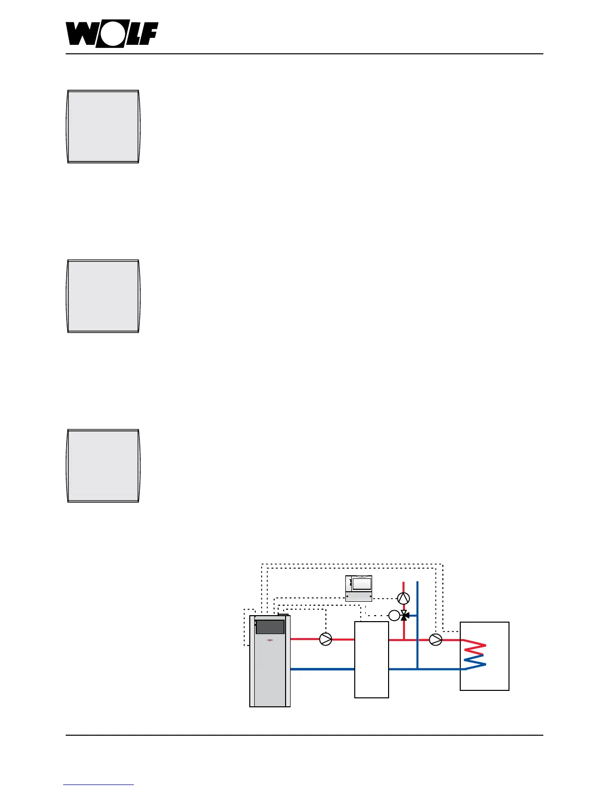
Hydraulic scheme:
Pump operating mode
Parameter HG06
HG06
0
Factory setting: 0
Setting range: 0 / 1 / 2
ZUP = Feed pump
SPL = Cylinder primary pump
SF = Cylinder sensor
SAF = Header sensor
KF = Boiler sensor
MKP = Mixer circuit pump
M = Mixer motor
MM = Mixer module
Oil condensing boiler
Cylinder
Low loss
header or
buffer
M
MM
SAF
ZUP
MKP
SPL
SF
KF