53
3062547_201507
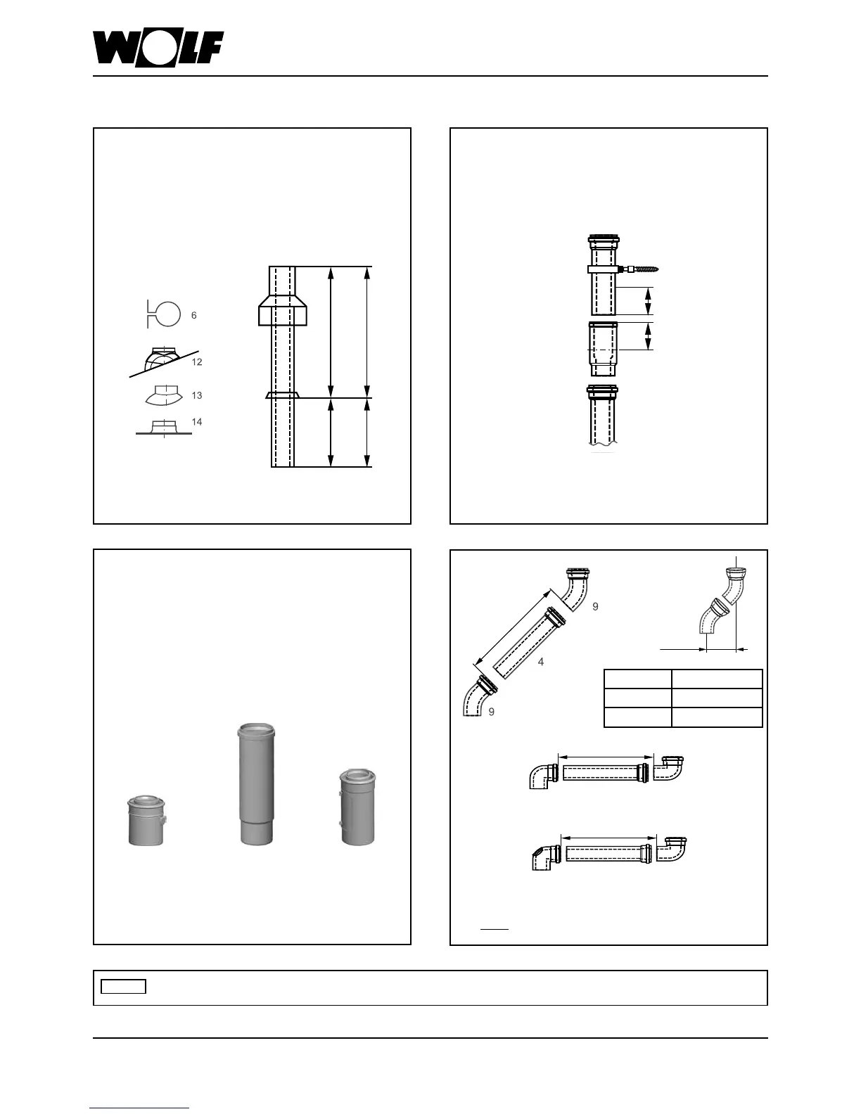
SupplementaryinstallationinstructionsforbalancedueDN80/125
During installation, slide the separator (8) fully into the coupling.
Push the next balanced ue (4) 50 mm (dim. "S") into the coupling
of the separator, and secure in this location, e.g. with pipe clips
DN 125 (5) or a xing screw on the air side.
Flat roof: Afx the ceiling outlet approx. Ø 130 mm (14) in the roof
cover.
Pitched roof: At (12), observe the installation instructions on the
cowl regarding roof pitches.
If an inspection aperture is required for the balanced ue, insert a
balanced ue with inspection aperture (3) (250 mm long).
Insert the roof outlet (7) from above through the roof and secure
vertically with (6) to a rafter or brickwork.
Installtheroofoutletonlyinitsoriginalcondition.Modications
are not permissible.
31. Design information
Wet or lubricate all air/ue gas joints prior to installation, e.g. using a grease without silicone.
NB
Fit connection adaptor with test nipple (2) to the oil condensing
boiler connection.
Separate the ue via a slide coupling (8)
For inspection purposes, undo and move the inspection piece clamp.
Undo and remove the inspection pipe cover.
Inspection piece (3)
Determine distance A. Length of balanced ue (4) always approx.
100 mm longer than distance A. Always trim the ue on the smooth
side, never on the coupling side.
Chamfertheueaftertrimming.