Position of fuses and plug connectors
PRINCESS – Edition: 17.02.2005
52
FIELD SERVICE MANUAL
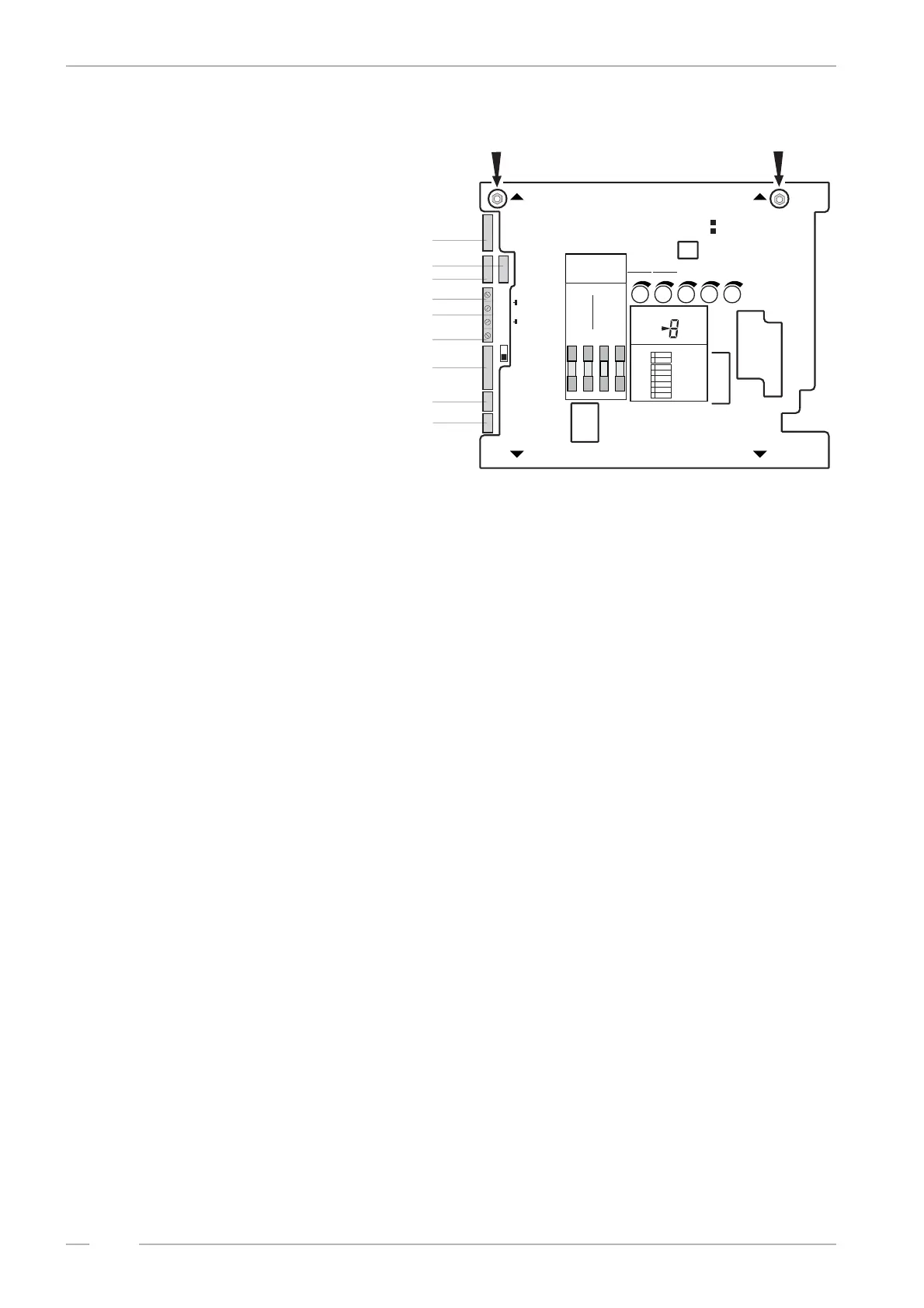
12.4 Position of fuses and plug connectors
Usually the jukeboxes are fitted
with fuses of DIN 41571 (5x20
mm) slow blow or medium blow.
Slow blow fuses of DIN standard
bear the letter T (T = ”Träge”) e.g.
T 4/250 means T = slow blow, 4
amps, 250 V maximum operating
voltage. Which fuses have to fit in
is printed on the power transformer
cover. Fast blow fuses (F = Flink)
are unsuitable for the jukebox.
The fuse holders on the amplifier
P.C.B. are also capable to hold fu-
ses of 6x32 mm size.
You will find the fuses behind the
amplifier cover plate. To remove
the plate first unplug the cable co-
ming from the mains transformer.
Next lose slightly both nuts on top
of the amplifier accessible through the holes in the cover plate (arrows). To remove the plate first
take the bottom side out of its hinges and then the top side.
Connection plan of the plug terminals:
! 1P09 - mechanism, SCC unit
! 1P06A - option
! 1P06B - option
! 2LP04 - external speakers, LH
! 2P04 - external speakers, ground
! 2RP04 - external speakers, RH
! 2P12 - Internal speakers
! 1P04 - CD sub transformer, CD player
! 1P03 - bubble tubes
Fuse Failure
Main fuse T 3,15,res. F6 A for 110/117 V. No illumination, machine completely dead.
Fuse F1: T4A supply 30V ~ The digital digit on the CD-control is dark. Power sup-
ply for CD player and control unit is interrupted. Credit
circuit via LED M is interrupted. If credits are still in
memory or free play is programmed; a CD will be
placed on turntable but is not spinning.
Fuse F2: T4A supply 26V ~
Fuse F3: T4A supply 26V ~
The colour tubes of the One More Time do not rotate,
the heating of the bubble tubes is off - no bubbles will
appear. Possibly defect of the power stage of the amp-
lifier.
Fuse F4: T4A supply +12 V= SCC unit dead - digital display dark (except red LED M
still lighting up on coin insertion). The LEDs K and Z
on the SCC unit are dark. No initialisations run after
power ON. The status display on the amplifier is dark.
CAUTION
TO REDUCETHE RISK
OF FIRE REPLACE ONLY
WITH SAMETYPE AND
RATING FUSE
Bass Treble
BGM
M
S
ONO
TEREO
ANAL HANNEL
TEREO
2-K / 2-C
S
S
F
ICHERUNG
USE
F1-F4
100-240V
50Hz/60Hz
117 V
60Hz
3,0 AMP
250 V AC
SLOW BLOW
T4A
30V~
AC
F1
26V~
AC
F2
26V~
AC
F3
12V=
DC
F4
IL
NTERNER AUTSPRECHER
NTERNAL PEAKER
IS
O
PTION
O
PTION
R
L
E
L
E
S
8/80W
XTERNER AUTSPRECHER
XTERNAL PEAKER
W
CD-T
CD-T
RAFO
RANSFORMER
B-TUBBLE UBES
N
T
ETZTRAFO
RANSFORMER
E
E
RWEITERUNG
XTENSION
F
RC
ERNREGLER
EMOTE- ONTROL
RS 232
BGM
I
R
I
R
NFRAROT- EGLER
NFRARED- EMOTE
A
O
LR
USGANG
UTPUT
E
CD
I
CD
LR
INGANG
NPUT
E
E
300mV
XTRA
XTRA
E
300mV
I
LR
INGANG
NPUT
M
M
IKROFON
ICROPHONE
MECHANIK
MECHANISM
DA
RC
ECKEL BNEHMEN
EMOVE OVER
DA
RC
ECKEL BNEHMEN
EMOVE OVER
I
C1
ntern
hannel
E
C
xtern
hannel
2
Verstärker K 99 0056041
Amplifier K 99 C-UL 0058484
1P09
1P06B
2P04
2LP04
2RP04
2P12
1P04
1P03
1P06A
AV C
RS232
M
ICRO
TAPE
MUTE
A/DNZEIGE ISPLAY
BGM
ok.
S/SCHALTER WITCHES
A/OUS FF
A/OUS FF
E/OIN N
E/OIN N
A
A
VC
VC
MODES
TEREO 2-K /2CANAL HANNEL
INPUT
CD
TAPE
BGM
1
1
3
5
2
2
4
6
SEPARATE
NORMAL
AUTO
VOLUME
RS232
MUTE
HIGH LOW
PARALLEL
SERVICE
AUS/OFF