Wall mounting
PRINCESS – Edition: 17.02.2005
5
OPERATING INSTRUCTIONS
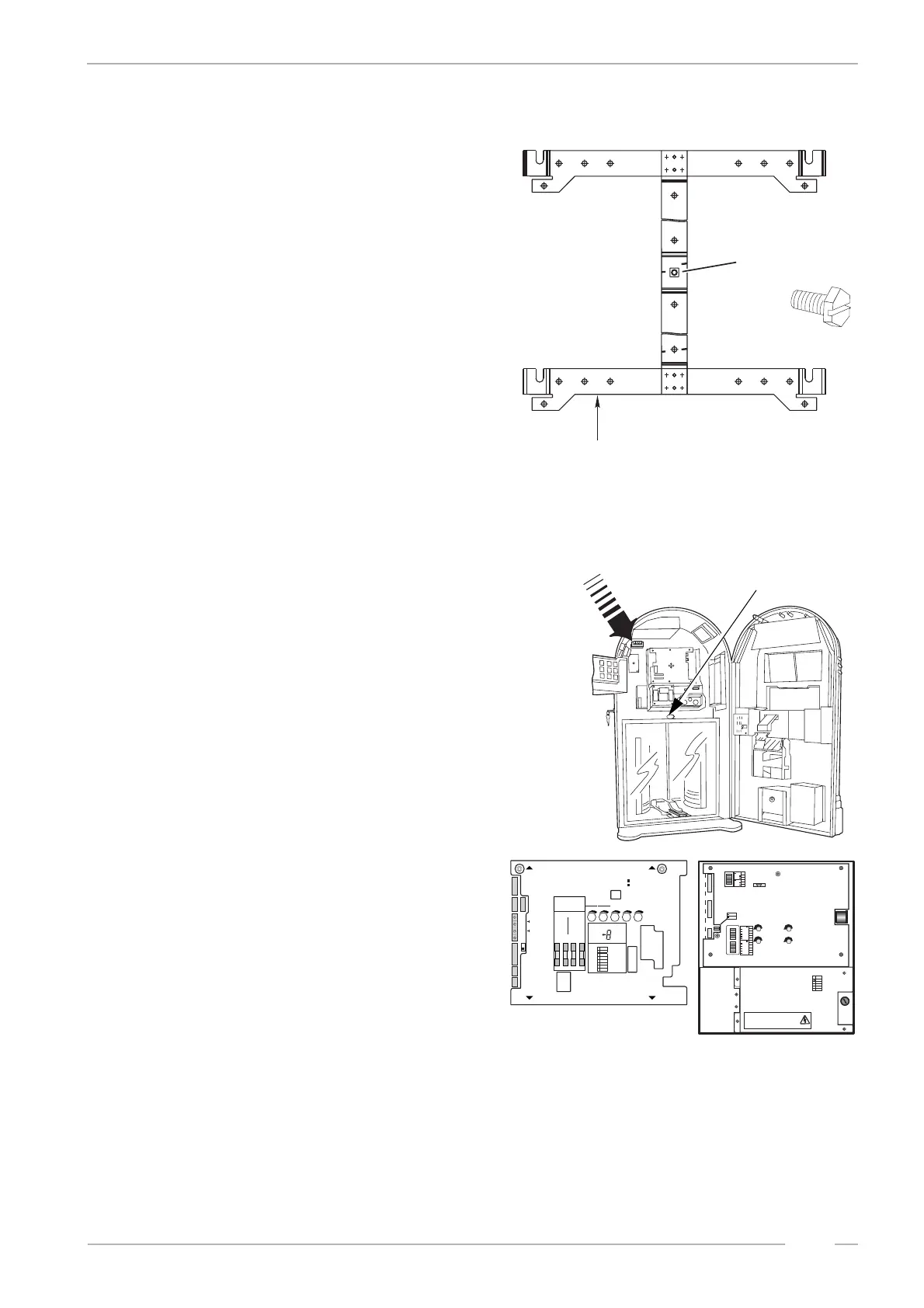
1.4 Wall mounting
Depending on the installed amplifier the weight
of the jukebox is 78kg (amplifier K99) to 85kg
(amplifier F91). Because of this take great pains
when you mount it on a wall. Use the delivered
mounting frame (part no. 0051361) and check
the structural quality of the wall. Calculate a se-
curity factor of 2 (170kg) for home use and a
factor of 4 (340kg) for public use when you se-
lect your dowels. Use all the dowel holes of the
frame. Contact your architect and a dowel ma-
nufacturer to select suitable mounting devices.
The manufacturer does not accept liability for
damages caused of not proper mounted machi-
nes!
Fasten the jukebox with the locking bolt which
you will find in the accessories.
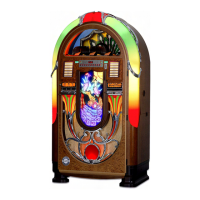
1.5 Speaker connection
To attain a good sound of the jukebox, take
care when connecting the speakers. Connect
the speakers to either the terminals inside of the
jukebox or to the terminals on the back side.
Pay attention of the correct polarity. The red ter-
minals belong to "+" the black ones to "-".
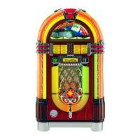
The jukebox can be delivered with two different
amplifiers F91 or K99. You can distinguish both
types by means of the product label inside the
door or compare your amplifier with the pictures
below here.
Both amplifiers may not be loaded with more
than 4Ω per channel. Less Ohm means more
load! The output of the amplifier K99 to a 4Ω
load is 55 Watts rms power at 1 % distortion, to
8Ω it is about 28 Watts, to 12Ω it is about 18
Watts.
The output of the amplifier F91 to a 4Ω load is
170Watts rms power, to 8Ω it is about 85 Watts,
to 12Ω it is about 57 Watts.
thread for
locking bolt
heights approx. 1.10m
hole for locking bolt
speaker terminals
inside
Verstärker-Sicherungen
210V - 240V
Si 1/Si 301
Si 2/Si 302
Si 102/Si 103
Si 100/Si 101
MT 4A
T 3,15A
100V - 117V
Si 1/Si 301
Si 2/Si 302
T5A
Si 102/Si 103
Si 100/Si 101
T3A
Zur Beachtung Nur Sicherungen mit gleicher Größe und
gleichem Wert verwenden um Schäden zuvermeiden.
Caution: To reduce the risk of fire replace only with
same type and rating fuses.
Achtung!
Vor Abnahme der Kappe den Netzstecker
ziehen!
Attention!
Pull power plug before opening protective
lid!
Leuchtstofflampen/
Flourescent Lamps
230V / 117V
/ Amplifier Fuses
Netzspannung
50/60 Hz
Mains Voltage
50/60 cps
240
230
210
100
220
117
Low Level
BGM
Mic.-Kit
L
R
Line Out
L
R
Input Tape
L
R
Input CD
Amplifier F91
0039155
BGM Level
R
L
LR
Clipping
P10
Remote
P10
Remote
P4
1
2
4
1
2
4
Tone
off on
Treble
Bass
1
2
4
8
16
32
1
2
4
8
16
32
Volume
off on
R
L
Mode
Input
CD
Stereo
Tape
2-Kanal
R
L
CAUTION
TO REDUCETHE RISK
OF FIRE REPLACE ONLY
WITH SAMETYPE AND
RATING FUSE
Bass Treble
BGM
M
S
ONO
TEREO
ANAL HANNEL
TEREO
2-K / 2-C
S
S
F
ICHERUNG
USE
F1 - F4
100-240V
50Hz/60Hz
117 V
60Hz
3,0 AMP
250 VAC
SLOW BLOW
T4A
30V~
AC
F1
26V~
AC
F2
26V~
AC
F3
12V=
DC
F4
IL
NTERNER AUTSPRECHER
NTERNAL PEAKER
IS
O
PTION
O
PTION
R
L
E
L
E
S
8
/80W
XTERNER
AUTSPRECHER
XTERNAL
PEAKER
W
CD-T
CD-T
RAFO
RANSFORMER
B-TUBBLE UBES
N
T
ETZTRAFO
RANSFORMER
E
E
RWEITERUNG
XTENSION
F
RC
ERNREGLER
EMOTE- ONTROL
RS 232
BGM
I
R
I
R
NFRAROT- EGLER
NFRARED- EMOTE
A
O
LR
USGANG
UTPUT
E
CD
I
CD
LR
INGANG
NPUT
E
E
300mV
XTRA
XTRA
E
300mV
I
LR
INGANG
NPUT
M
M
IKROFON
ICROPHONE
MECHANIK
MECHANISM
DA
RC
ECKEL BNEHMEN
EMOVE OVER
DA
RC
ECKEL BNEHMEN
EMOVE OVER
AVC
RS232
M
ICRO
TAPE
MUTE
A/DNZEIGE ISPLAY
BGM
ok.
S/SCHALTER WITCHES
A/OUS FF
A/OUS FF
E/OIN N
E/OIN N
AVC
MODES
TEREO 2-K /2CANAL HANNEL
INPUTCD
T
APE
BGM
1
1
3
5
2
2
4
6
I
C1
ntern
hannel
E
C
xtern
hannel
2
Verstärker K 99
0056041
Amplifier K 99 C-UL
0058484
K99
F91