The first power ON
PRINCESS – Edition: 17.02.2005
53
FIELD SERVICE MANUAL
12.5 The first power ON
The mains switch is located at the rear
side of the amplifier and thus it is on
the rear side of the jukebox. For wall-
boxes it is possible to connect an ex-
ternal mains switch to the amplifier
accessible then from the side. In posi-
tion ‘I’ jukebox and amplifier are swit-
ched on.
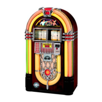
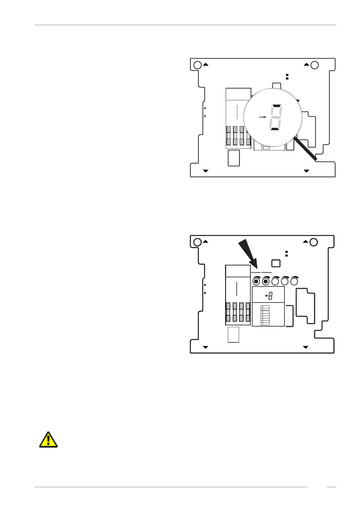
Up to approx. 1 sec. after power on
random segments of the status display
will light. Followed by displaying the
version number of the amplifier soft-
ware (1.0 or higher). Then the bottom
segment for “ok.” and the upper seg-
ment for MUTE will light. The amplifier
is now in STANDBY MODE. Depen-
ding on other enabled options more
segments may light as well (e.g.
AVC).
12.6 Volume control
You can control the volume of the
jukebox from different points at the
same time:
! With the pots Vol. 1 and Vol. 2 on
the amplifier.
! With an optional connectable IR re-
mote control.
! With the pots of the control box at
the rear side of the jukebox.
The device from which the volume is
changed determines it.
The volume control unit can be taken
out and may be mounted at another
place as a remote control. Its cable
may be extended as required with any
kind of wire. The voltages of the cont-
rol wires are 5V DC.
The control box has two volume knobs (Intern / Channel 1 and Extern / Channel 2). In position ”Ste-
reo” the knob “Intern / Channel 1” is effective for the internal speakers. The knob Extern / Channel 2
is controlling the volume of the RCA outputs for an optional external amplifier. In DIP switch position
”2 Channel” the channels 1 (RH) and 2 (LH) are controlled separately.
ATTENTION! The pots Vol. 1 and Vol. 2 on the amplifier are not effective if the wire control
box is connected.
CAUTION
TO REDUCETHE RISK
OF FIRE REPLACE ONLY
WITH SAMETYPE AND
RATING FUSE
Bass Treble
BGM
M
S
ONO
TEREO
ANAL HANNEL
TEREO
2-K / 2-C
S
S
F
ICHERUNG
USE
F1-F4
100-240V
50Hz/60Hz
117 V
60Hz
3,0 AMP
250 V AC
SLOW BLOW
T4A
30V~
AC
F1
26V~
AC
F2
26V~
AC
F3
12V=
DC
F4
IL
NTERNER AUTSPRECHER
NTERNAL PEAKER
IS
O
PTION
O
PTION
R
L
E
L
E
S
8 / 80 W
XTERNER AUTSPRECHER
XTERNAL PEAKER
W
CD-T
CD-T
RAFO
RANSFORMER
B-TUBBLE UBES
N
T
ETZTRAFO
RANSFORMER
E
E
RWEITERUNG
XTENSION
F
RC
ERNREGLER
EMOTE- ONTROL
RS 232
BGM
I
R
I
R
NFRAROT- EGLER
NFRARED- EMOTE
A
O
LR
USGANG
UTPUT
E
CD
I
CD
LR
INGANG
NPUT
E
E
300mV
XTRA
XTRA
E
300mV
I
LR
INGANG
NPUT
M
M
IKROFON
ICROPHONE
MECHANIK
MECHANISM
DA
RC
ECKEL BNEHMEN
EMOVE OVER
DA
RC
ECKEL BNEHMEN
EMOVE OVER
S/SCHALTER WITCHES
A/OUS FF
A/OUS FF
E/OIN N
E/OIN N
AVC
MODES
TEREO 2-K /2CANAL HANNEL
INPUTCD
T
APE
BGM
1
1
3
5
2
2
4
6
I
C1
ntern
hannel
E
C
xtern
hannel
2
Verstärker K 99 0056041
Amplifier K 99 C-UL 0058484
A/DNZEIGE ISPLAY
AVC
RS232
M
ICRO
TAPE
MUTE
BGM
ok.
AVC
S232
M
ICRO
TAPE
MUTE
BGM
ok.
CAUTION
TO REDUCETHE RISK
OF FIRE REPLACE ONLY
WITH SAMETYPE AND
RATING FUSE
B
ass
T
reble
BGM
M
S
ONO
TEREO
ANAL HANNEL
TEREO
2-K / 2-C
S
S
F
ICHERUNG
USE
F1-F4
100-240V
50Hz/60Hz
117 V
60Hz
3,0 AMP
250 V AC
SLOW BLOW
T4A
30V~
AC
F1
26V~
AC
F2
26V~
AC
F3
12V=
DC
F4
IL
NTERNER AUTSPRECHER
NTERNAL PEAKER
IS
O
PTION
O
PTION
R
L
E
L
E
S
8/80W
XTERNER AUTSPRECHER
XTERNAL PEAKER
W
CD-T
CD-T
RAFO
RANSFORMER
B-T
UBBLE UBES
N
T
ETZTRAFO
RANSFORMER
E
E
RWEITERUNG
XTENSION
F
RC
ERNREGLER
EMOTE- ONTROL
RS 232
BGM
I
R
I
R
NFRAROT- EGLER
NFRARED- EMOTE
A
O
LR
USGANG
UTPUT
E
CD
ICD
LR
INGANG
NPUT
E
E
300mV
XTRA
XTRA
E
300mV
I
LR
INGANG
NPUT
M
M
IKROFON
ICROPHONE
M
ECHANIK
M
ECHANISM
DA
RC
ECKEL BNEHMEN
EMOVE OVER
DA
RC
ECKEL BNEHMEN
EMOVE OVER
I
C1
ntern
hannel
E
C2
xtern
hannel
Verstärker K 99
Amplifier K 99 C-UL
AVC
RS232
M
ICRO
TAPE
MUTE
A/DNZEIGE ISPLAY
BGM
ok.
S/SCHALTER WITCHES
A/OUS FF
A/OUS FF
E/OIN N
E/OIN N
A
A
VC
VC
MODES
TEREO 2-K /2CANAL HANNEL
INPUT
CD
TAPE
BGM
1
1
3
5
2
2
4
6
SEPARATE
NORMAL
AUTO
VOLUME
RS232
MUTE
HIGH LOW
PARALLEL
SERVICE
AUS/OFF