Contents
xii 975-0004-01-02 Rev D
Automatic/Manual Battery Equalization (EQ) and Low
Voltage Reconnect (LVR) Jumper- - - - - - - - - - - - - - 21
Adjusting the C-Series Voltage Settings- - - - - - - - - - - - - - - - - 22
Setting Voltage Parameters for Charge Control Mode- - - - - 22
Setting Voltage Parameters for Load Control Mode - - - - - - 24
Setting Voltage Parameters Diversion Control Mode - - - - - 26
Setting Voltage Parameters for Alkaline Batteries - - - - - - - 26
Using a Digital Voltmeter to Adjust Voltage Settings - - - - - 28
Equalization Charging- - - - - - - - - - - - - - - - - - - - - - - - - - - - - 30
Manual Equalization - - - - - - - - - - - - - - - - - - - - - - - - - - - 31
Automatic Equalization - - - - - - - - - - - - - - - - - - - - - - - - - 32
Terminating the Equalization Process - - - - - - - - - - - - - - - 33
Temperature Compensation - - - - - - - - - - - - - - - - - - - - - - - - - 33
Temperature Compensation Based on Battery Type - - - - - - 34
Automatic Battery Temperature Compensation - - - - - - - - - 34
Manual Battery Temperature Compensation - - - - - - - - - - - 36
Grounding- - - - - - - - - - - - - - - - - - - - - - - - - - - - - - - - - - - - - 37
Wiring - - - - - - - - - - - - - - - - - - - - - - - - - - - - - - - - - - - - - - - 38
DC Terminal Connector Locations - - - - - - - - - - - - - - - - - 38
Terminal Torque Requirements- - - - - - - - - - - - - - - - - 39
Wire Size and Over-current Protection Requirements - - - - - 39
Current Rating - - - - - - - - - - - - - - - - - - - - - - - - - - - - 39
Minimum Recommended Wire Gauge - - - - - - - - - - - - 40
Surge Protection - - - - - - - - - - - - - - - - - - - - - - - - - - - 40
Over-current Protection - - - - - - - - - - - - - - - - - - - - - - 41
Long-distance wire runs- - - - - - - - - - - - - - - - - - - - - - 42
Maximum One-way Distance and Wire Size - - - - - - - - 42
PV Charge Control Mode Wiring - - - - - - - - - - - - - - - - - - 44
Diversion Control Mode Wiring - - - - - - - - - - - - - - - - - - - 46
DC Load Control Mode Wiring- - - - - - - - - - - - - - - - - - - - 48
Installing Optional Accessories- - - - - - - - - - - - - - - - - - - - - - - 50
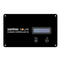
Installing a Digital Display- - - - - - - - - - - - - - - - - - - - - - - 50
Installing the Battery Temperature Sensor - - - - - - - - - - - - 51
Reinstalling the Faceplate - - - - - - - - - - - - - - - - - - - - - - - - - - 52
 Loading...