June 2014
4-16
Xerox® Phaser® 3052/3260 Service Manual
REP 1.9
Repairs
Replacement
NOTE: Tapered Plastic Screws and Round Machine Screws are used to hold the PWB to the
frame. Make sure that the Plastic Screws go into plastic components and Machine Screws go
into the metal frame.
Install the components in the reverse of removal.
1. Install the new Drive Motor (4 screws).
NOTE: The Frame is flexible and can be bowed out if the screws are not tightened in the
correct order.
Reinstall the Frame as follows so it seats flush against the printer internal modules.
2. Align the Frame on to the internal modules and shafts.
NOTE: Do Not fully tighten the screws in Step 3 until instructed.
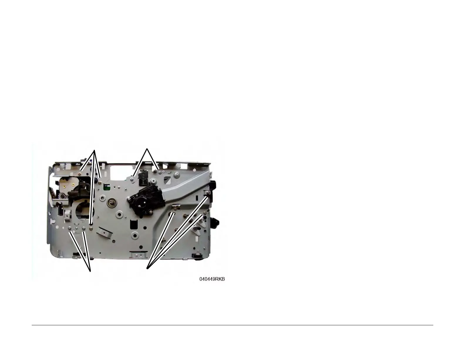
3. Install, but do not tighten, the following module screws (Figure 9):
a. The Fuser Module screws (2)
b. The Front Paper Path Module screws (3)
Figure 9 Frame Screw Installation
4. On the bottom of the Printer (Figure 7):
a. Install the Ground Clip and screw (1).
Tighten the screw.
b. Connect the Drive Motor Connector.
Step 3a
Step 5b
Step 5c
Step 3b