KCU105 Board User Guide www.xilinx.com 68
UG917 (v1.4) September 25, 2015
Chapter 1: KCU105 Evaluation Board Features
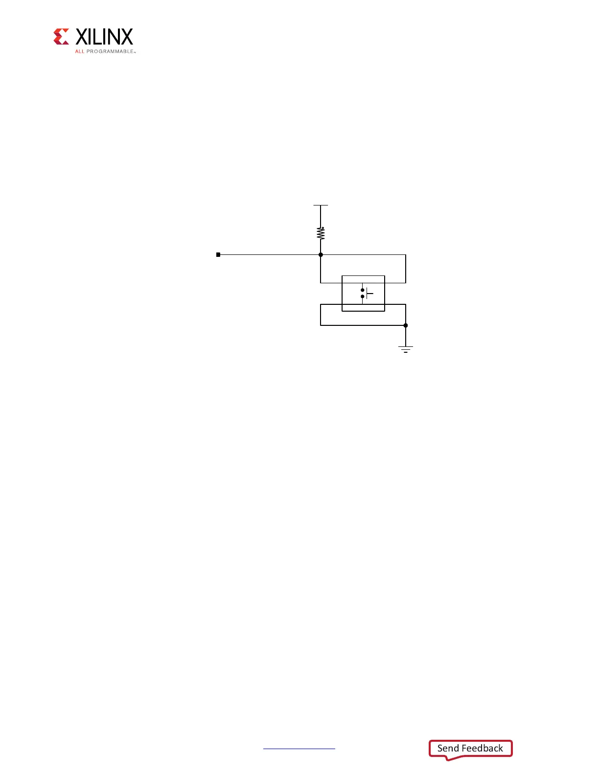
Program_B Pushbutton Switch
[Figure 1-2, callout 27]
Switch SW4 grounds the XCKU040 device U1 PROGRAM_B pin when pressed. This action
clears the FPGA programmable logic configuration. The FPGA_PROG_B signal is connected
to the XCKU040 device U1 pin T7. For further configuration details, see UltraScale
Architecture Configuration User Guide (UG570) [Ref 3]. Figure 1-33 shows switch SW4.
FPGA Mezzanine Card Interface
[Figure 1-2, callouts 33, 34]
The KCU105 evaluation board supports the VITA 57.1 FPGA mezzanine card (FMC)
specification by providing subset implementations of the high pin count (HPC) connector at
J22 and low pin count (LPC) version at J2. Both connectors use a 10 x 40 form factor. The
HPC connector is populated with 400 pins, while the LPC connector is partially populated
with 160 pins. The connectors are keyed so that a mezzanine card, when installed in either
of these FMC connectors on the KCU105 evaluation board, faces away from the board.
Connector type:
• Samtec SEAF Series, 1.27 mm (0.050 in) pitch. Mates with SEAM series connector
More information about SEAF series connectors is available at the Samtec, Inc. website
[Ref 34].
More information about the VITA 57.1 FMC specification is available at the VITA FMC
Marketing Alliance website [Ref 35].
X-Ref Target - Figure 1-33
Figure 1-33: Program_B Pushbutton Switch SW4
3
3
3
3
3XVKEXWWRQ
*1'
7/()4*
6:
5
.
)3*$B352*B%
9&&9
:
8*BB