Installing the Board in a PC Chassis
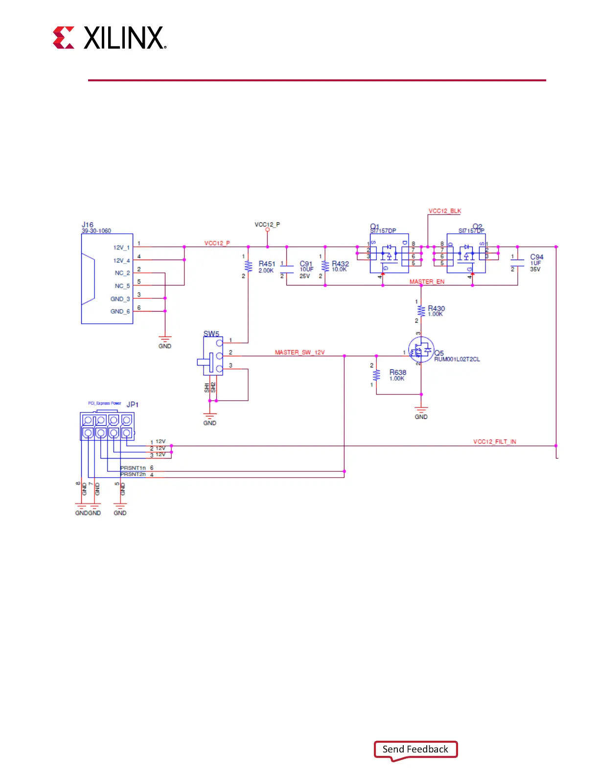
The VCU128 board 12V power input circuitry allows 12V to be applied through one of two
connectors, J16 (typically used with the stand-alone VCU128 power adapter) or JP1, as shown in
the following gure.
Figure 3: 12V Power Entry
X22058-121318
Installaon of the VCU128 board inside a computer chassis is required when developing or
tesng PCI Express
®
funconality. When the VCU128 board is used inside a computer chassis
(i.e., plugged in to a PCIe
®
slot), power is provided by choosing one of two mutually exclusive
ATX power supply cables as described in this secon (use one cable or the other).
• The ATX power supply 4-pin (1x4) peripheral connector, which requires using the ATX
adapter cable (see the following gure) to connect to J16 on the VCU128 board. The Xilinx
®
part number for this cable is 2600304. See ATX Power Supply Adapter Cable.
Chapter 2: Board Setup and Configuration
UG1302 (v1.0) December 21, 2018 www.xilinx.com
VCU128 Board User Guide 14