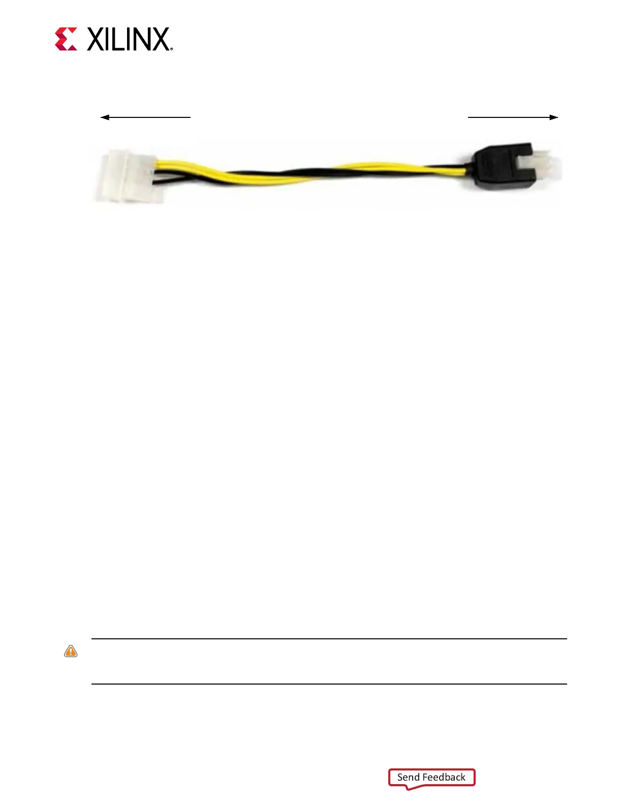
Figure 4: ATX Power Supply Adapter Cable
To ATX 4-Pin Peripheral
Power Connector
To J16 on VCU128 Board
X21955-121918
• The ATX supply 8-pin (2x4) PCIe power connector, which plugs into JP1 on the VCU128
board.
Steps to Install Board
To install the board in a PC chassis:
1. On the VCU128 board, remove the ve screws retaining the ve rubber feet and standos,
and the PCIe bracket. Reinstall the PCIe
®
bracket using two of the previously removed
screws.
2. Power down the host computer and remove the power cord from the PC.
3. Open the PC chassis following the instrucons provided with the PC.
4. The VCU128 board has a large cooling fan that requires two adjacent PCIe slots. Ensure the
slot adjacent to the front of the board is free of obstrucons.
5. Remove the PCIe expansion slot cover (at the back of the chassis) which aligns with the
VCU128 PCIe bracket, by removing the screws on the top and boom of the cover.
6. Plug the VCU128 board into the appropriate open slot.
7. Install the top mounng bracket screw into the PC expansion cover retainer bracket to secure
the VCU128 board in its slot.
8. If using the ATX supply 4-pin (1x4) peripheral connector, connect power to the VCU128
board using the ATX power supply adapter cable as shown in Figure 4.
a. Plug the 6-pin 2 x 3 Molex connector end of the adapter cable into J16 on the VCU128
board.
b. Plug the 4-pin 1 x 4 peripheral power connector from the ATX power supply into the 4-
pin adapter connector end of the cable.
CAUTION
! Do NOT plug a PC ATX power supply 6-pin connector into J16 on the VCU128 evaluaon
board. The ATX 6-pin connector has a dierent pinout than J16. Connecng an ATX 6-pin connector
into J16 damages the VCU128 evaluaon board and voids the board warranty.
c. Slide the VCU128 board power switch SW5 to the ON posion. The PC can now be
powered on.
Chapter 2: Board Setup and Configuration
UG1302 (v1.0) December 21, 2018 www.xilinx.com
VCU128 Board User Guide 15