User GPIO
[Figure 2, callout 27, 28, 29]
The VCU128 board provides the following user and general purpose I/O capabilies.
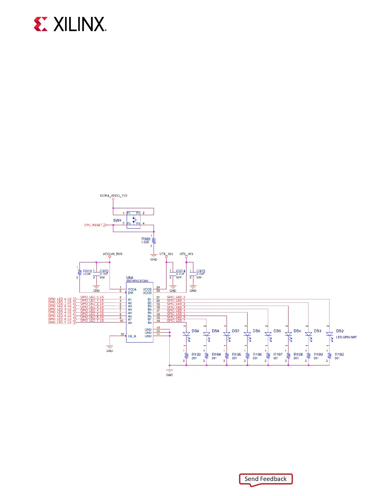
• Eight user LEDs (callout 28)
○ GPIO_LED[7-0]: DS9, DS8, DS7, DS6, DS5, DS4, DS3, DS2
• CPU_RESET/GPIO pushbuon switch (callout 29)
○ CPU_RESET: SW4
The following gure shows the GPIO circuits.
Figure 26: User GPIO
X21972-112918
GPIO Connections to FPGA U1
The following table lists the GPIO connecons to FPGA U1.
Chapter 3: Board Component Descriptions
UG1302 (v1.0) December 21, 2018 www.xilinx.com
VCU128 Board User Guide 76