26 www.xilinx.com VC7222 IBERT Getting Started Guide
UG971 (v5.0) June 12, 2014
Chapter 1: VC7222 IBERT Getting Started Guide
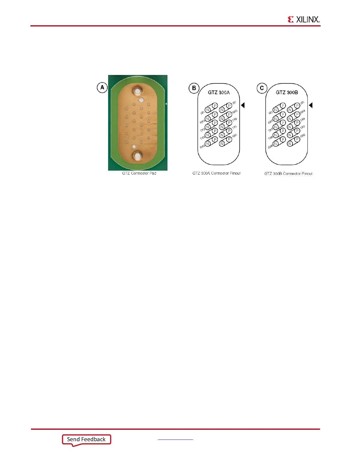
All GTZ transceiver pins and reference clock pins are routed from the FPGA to a connector
pad which interfaces with the Samtec BullsEye connectors. Figure 1-21 A shows the
connector pad, and Figure 1-21 B and C show the connectors pinout.
The SuperClock-2 module provides LVDS clock outputs for the GTH and the GTZ
transceivers reference clock in the IBERT demonstration. For the GTZ IBERT
demonstration, the output clock frequency is preset to 255.00 MHz. See the description for
connecting the SuperClock-2 module, page 9, for more details.
X-Ref Target - Figure 1-21
Figure 1-21: A - GTZ Connector Pad. B and C - GTZ Connector Pinout

 Loading...


