EasyManuals Logo

Xilinx Virtex-7 VC7203 User Manual

Xilinx Virtex-7 VC7203
77 pages
To Next Page IconTo Next Page
To Previous Page IconTo Previous Page
Page #14 background imageLoading...
Page #14 background image
14 www.xilinx.com VC7203 GTX Transceiver Characterization Board
UG957 (v1.3) October 17, 2014
Chapter 1: VC7203 Board Features and Operation
The fan power connections are detailed in Table 1-5:
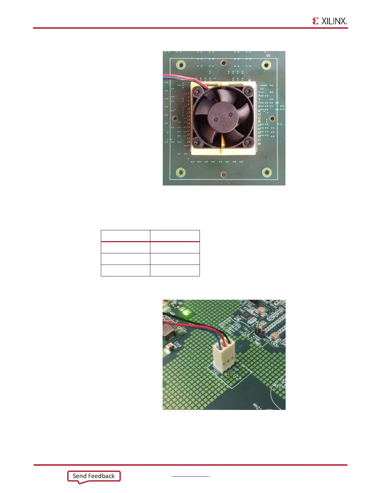
Figure 1-6 shows the heatsink fan power connector J121.
X-Ref Target - Figure 1-5
Figure 1-5: Active FPGA Heatsink
Table 1-5: Fan Power Connections
Fan Wire Header Pin
Black J121.1 - GND
Red J121.2 - 12V
Blue J121.3 - NC
X-Ref Target - Figure 1-6
Figure 1-6: Heatsink Fan Power Connector J121
UG957_c1_05_100712
UG957_c1_06_100712
Send Feedback

Questions and Answers:

Question and Answer IconNeed help?

Do you have a question about the Xilinx Virtex-7 VC7203 and is the answer not in the manual?

Xilinx Virtex-7 VC7203 Specifications

General IconGeneral
FPGA FamilyVirtex-7
TransceiverGTH
GTH Transceivers16
Maximum Data Rate13.1 Gbps
Transceivers16
Maximum Transceiver Speed13.1 Gbps
Maximum User I/O600
Process Technology28nm
Block RAM38 Mb
Power Supply Voltage0.9V
Operating Temperature RangeIndustrial

Related product manuals