ZC706 Evaluation Board User Guide www.xilinx.com 47
UG954 (v1.5) September 10, 2015
Feature Descriptions
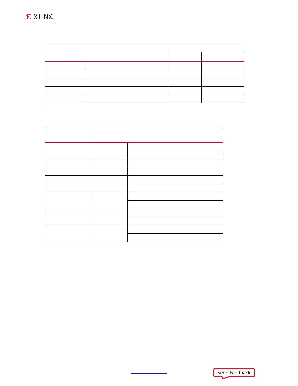
Table 1-18 lists the SFP+ module control and status connections to the AP SoC.
For additional information about the enhanced Small Form Factor Pluggable (SFP+)
module, see the SFF-8431 specification [Ref 23].
10/100/1000 Mb/s Tri-Speed Ethernet PHY (PL)
[Figure 1-2, callout 15]
The ZC706 evaluation board uses the Marvell Alaska PHY device (88E1116R) at U51 for
Ethernet communications at 10 Mb/s, 100 Mb/s, or 1000 Mb/s. The board supports RGMII
mode only. The PHY connection to a user-provided Ethernet cable is through a Halo
HFJ11-1G01E RJ-45 connector (P3) with built-in magnetics.
On power-up, or on reset, the PHY is configured to operate in RGMII mode with PHY
address 0b00111 using the settings shown in Table 1-19. These settings can be overwritten
via software commands passed over the MDIO interface.
Table 1-17: AP SoC U1 to SFP+ Module Connections
AP SoC (U1) Pin Schematic Net name
SFP+ Module (P2)
Pin Name
Y5 SFP_RX_N 12 RD_N
Y6 SFP_RX_P 13 RD_P
W4 SFP_TX_P 18 TD_P
W3 SFP_TX_N 19 TD_N
AA18 SFP_TX_DISABLE_TRANS 3 TX_DISABLE
Table 1-18: SFP+ Module Control and Status Connections
SFP Control/ Status
Signal
Board Connection
SFP_TX_FAULT Test Point J23
High = Fault
Low = Normal operation
SFP_TX_DISABLE Jumper 17
Off = SFP Disabled
On = SFP enabled
SFP_MOD_DETECT Test Point J24
High = Module not present
Low = Module present
SFP_RS0 Jumper 56
Jumper pins 1-2 = Full RX bandwidth
Jumper pins 2-3 = Reduced RX bandwidth
SFP_RS1 Jumper 55
Jumper pins 1-2 = Full TX bandwidth
Jumper pins 2-3 = Reduced TX bandwidth
SFP_LOS Test Point J25
High = Loss of receiver signal
Low = Normal operation