ZC706 Evaluation Board User Guide www.xilinx.com 58
UG954 (v1.5) September 10, 2015
Feature Descriptions
°
GPIO_DIP_SW[3:0] SW12
• Two user GPIO male pin headers (callout 26)
• 2 x 6 0.1 in. pitch PMOD1 J57
• 2 x 6 0.1 in. pitch PMOD2 J58
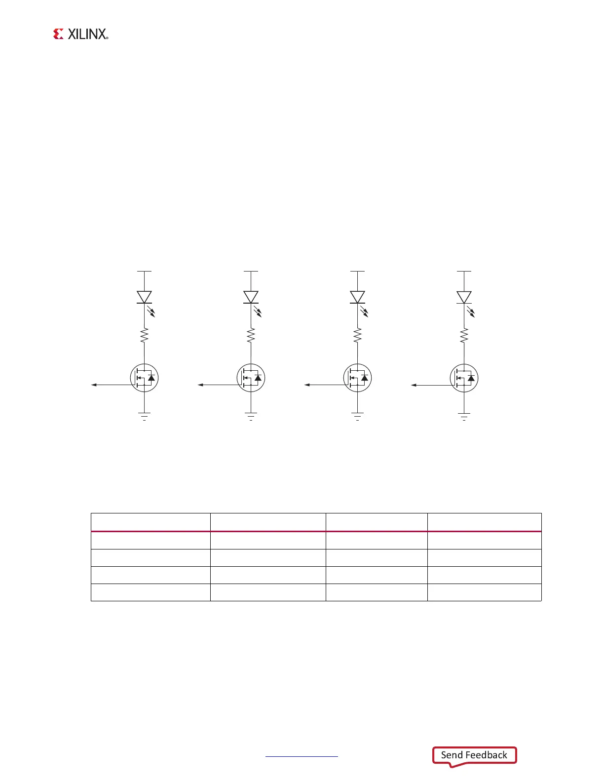
User LEDs
[Figure 1-2, callout 22]
The ZC706 evaluation board supports four user LEDs connected to XC7Z045 AP SoC Banks
11, 33, and 35. Figure 1-25 shows the user LED circuits.
Table 1-28 lists the user LED connections to XC7Z045 AP SoC U1.
X-Ref Target - Figure 1-25
Figure 1-25: User LEDs
UG954_c1_25_041113
1
3
2
1
2
1
2
Q7
NDS331N
460 mW
DS8
VCC3V3
R390
261Ω
0.1W
1%
GND
1
3
2
Q8
NDS331N
460 mW
DS9
VCC3V3
R391
261Ω
0.1W
1%
GND
1
3
2
Q9
NDS331N
460 mW
DS10
VCC3V3
R392
261Ω
0.1W
1%
GND
GPIO_LED_
CENTER
GPIO_LED_
RIGHT
GPIO_LED_0GPIO_LED_
LEFT
1
2
1
2
1
2
1
2
1
3
2
Q30
NDS331N
460 mW
DS35
VCC3V3
R544
261Ω
0.1W
1%
GND
1
2
1
2
Table 1-28: User LED Connections to XC7Z045 AP SoC U1
XC7Z045 AP SoC (U1) Pin Net Name I/O Standard LED Reference
Y21 GPIO_LED_LEFT LVCMOS25 DS8
G2 GPIO_LED_CENTER LVCMOS25 DS9
W21 GPIO_LED_RIGHT LVCMOS25 DS10
A17 GPIO_LED_0 LVCMOS25 DS35