ZC706 Evaluation Board User Guide www.xilinx.com 49
UG954 (v1.5) September 10, 2015
Feature Descriptions
The data sheet can be obtained under NDA with Marvell. Contact information can be found
at their website [Ref 24].
For additional information on the Zynq-7000 AP SoC device gigabit Ethernet controller, see
Zynq-7000 All Programmable SoC Overview (DS190
) and Zynq-7000 All Programmable SoC
Technical Reference Manual (UG585
).
USB-to-UART Bridge
[Figure 1-2, callout 17]
The ZC706 evaluation board contains a Silicon Labs CP2103GM USB-to-UART bridge device
(U52) which allows a connection to a host computer with a USB port. The USB cable is
supplied in the ZC706 evaluation kit (Standard-A end to host computer, Type Mini-B end to
ZC706 evaluation board connector J21). The CP2103GM is powered by the USB 5V provided
by the host PC when the USB cable is plugged into the USB port on the ZC706 evaluation
board.
The CP2013GM TX and RX pins are wired to the UART_1 IP block within the XC7Z045 AP SoC
PS I/O Peripherals set. The XC7Z045 AP SoC supports the USB-to-UART bridge using two
signal pins: Transmit (TX) and Receive (RX).
Silicon Labs provides royalty-free Virtual COM Port (VCP) drivers for the host computer.
These drivers permit the CP2103GM USB-to-UART bridge to appear as a COM port to
communications application software (for example, TeraTerm or HyperTerm) that runs on
the host computer. The VCP device drivers must be installed on the host PC prior to
establishing communications with the ZC706 evaluation board.
The USB Connector pin assignments and signal definitions between J21 and U52 are listed
in Table 1-21.
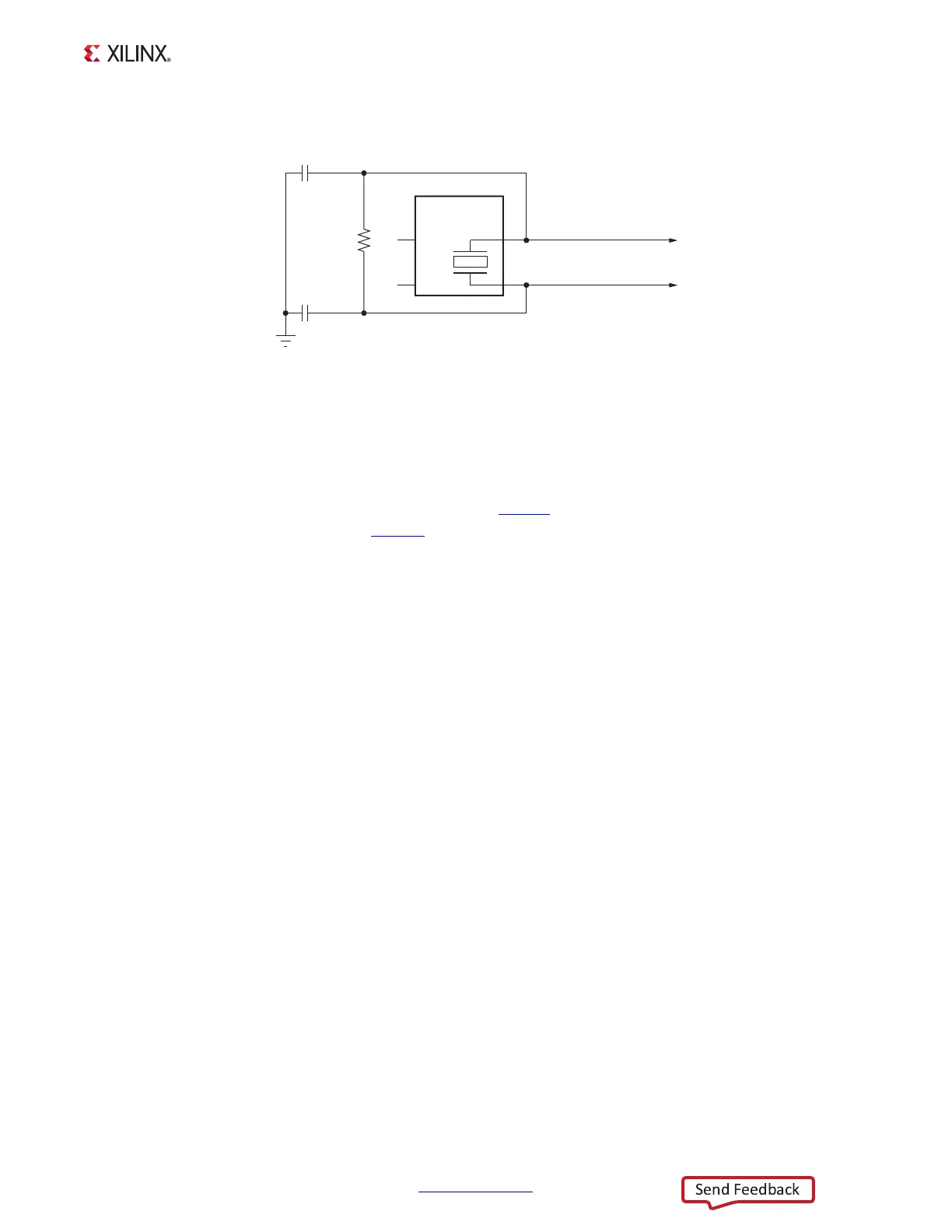
X-Ref Target - Figure 1-20
Figure 1-20: Ethernet PHY Clock Source
UG954_c1_20_041113
GND
R355
DNP
C495
18 pF 50V
NPO
C494
18 pF 50V
NPO
PHY XTAL OUT
X1
25.00 MHz
50 PPM
PHY XTAL IN
3
4
1
2
1
2
12
12
NC
NC