ZCU111 Board User Guide 78
UG1271 (v1.1) August 6, 2018 www.xilinx.com
Chapter 3: Board Component Descriptions
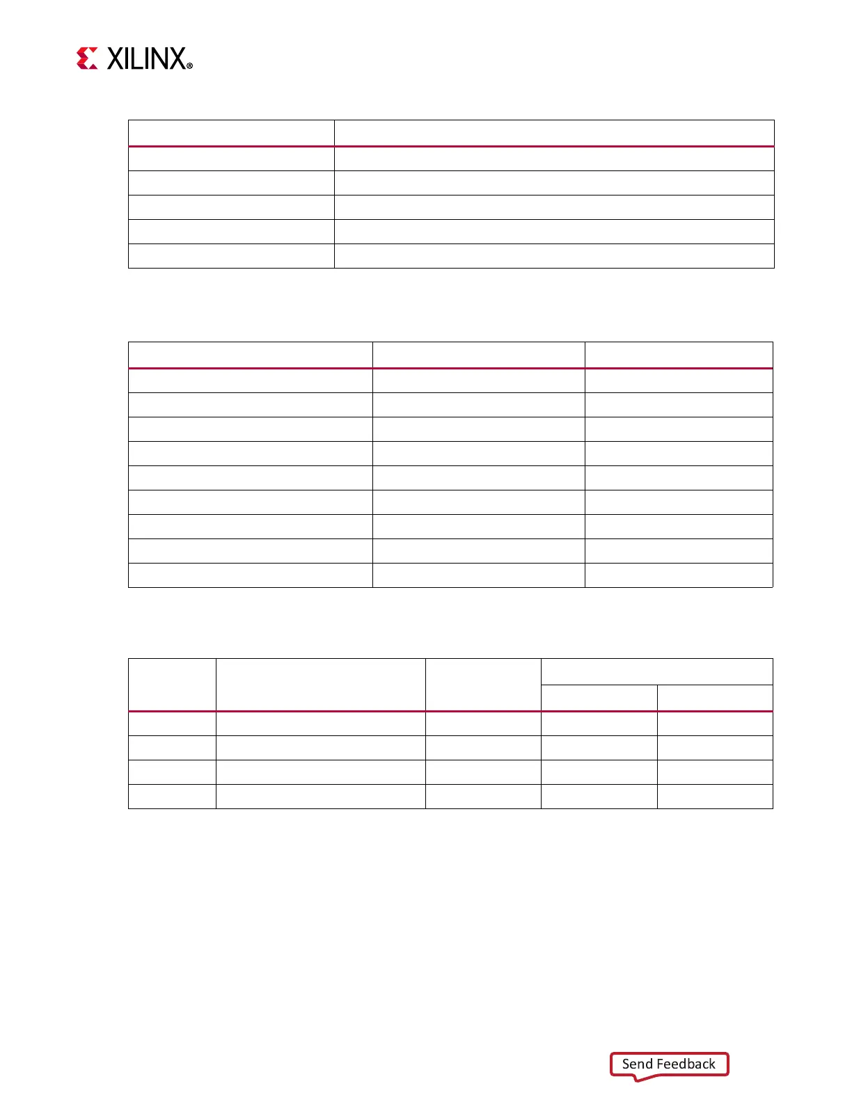
The M.2 adapter tie-offs as implemented on the ZCU111 board are listed in Tabl e 3-2 7 .
The M.2 U40 connector to RFSoC connections are listed in Tab le 3 - 28.
For more information, see PCI_Express_M.2_Specification_Rev1.1_TS_12092016_NCB
[Ref 21].
9GND
7NC
5NC
3GND
1GND
Table 3-27: M.2 U40 Connector Tie-offs
M.2 Signal Name ZCU111 Tie-Off U40 Pin
SUSCLK No connect 68
ALERT# No connect 44
SMB_DATA No connect 42
SMB_CLK No connect 40
DEVSLP GND 38
DAS/DSS DNP Res to GND 10
PEDET No connect 69
SATA-A GTR TX 49, 47
SATA-B GTR RX 43, 41
Table 3-28: M.2 U40 Connections to the XCZU28DR RFSoC
XCZU28DR
(U1) Pin
Net Name I/O Standard
M.2 Connector U40
Pin Number Pin Name
AD36 GT3_SATA1_TX_P (1) 49 SATA-A+
AD37 GT3_SATA1_TX_N (1) 47 SATA-A-
AC38 GT3_SATA1_RX_P (1) 41 SATA-B+
AC39 GT3_SATA1_RX_N (1) 43 SATA-B-
Notes:
1. Series capacitor coupled, MGT I/F, I/O standards do not apply.
Table 3-26: M.2 Connector U40 Pinout (Cont’d)
Pin Signal