ZCU111 Board User Guide 84
UG1271 (v1.1) August 6, 2018 www.xilinx.com
Chapter 3: Board Component Descriptions
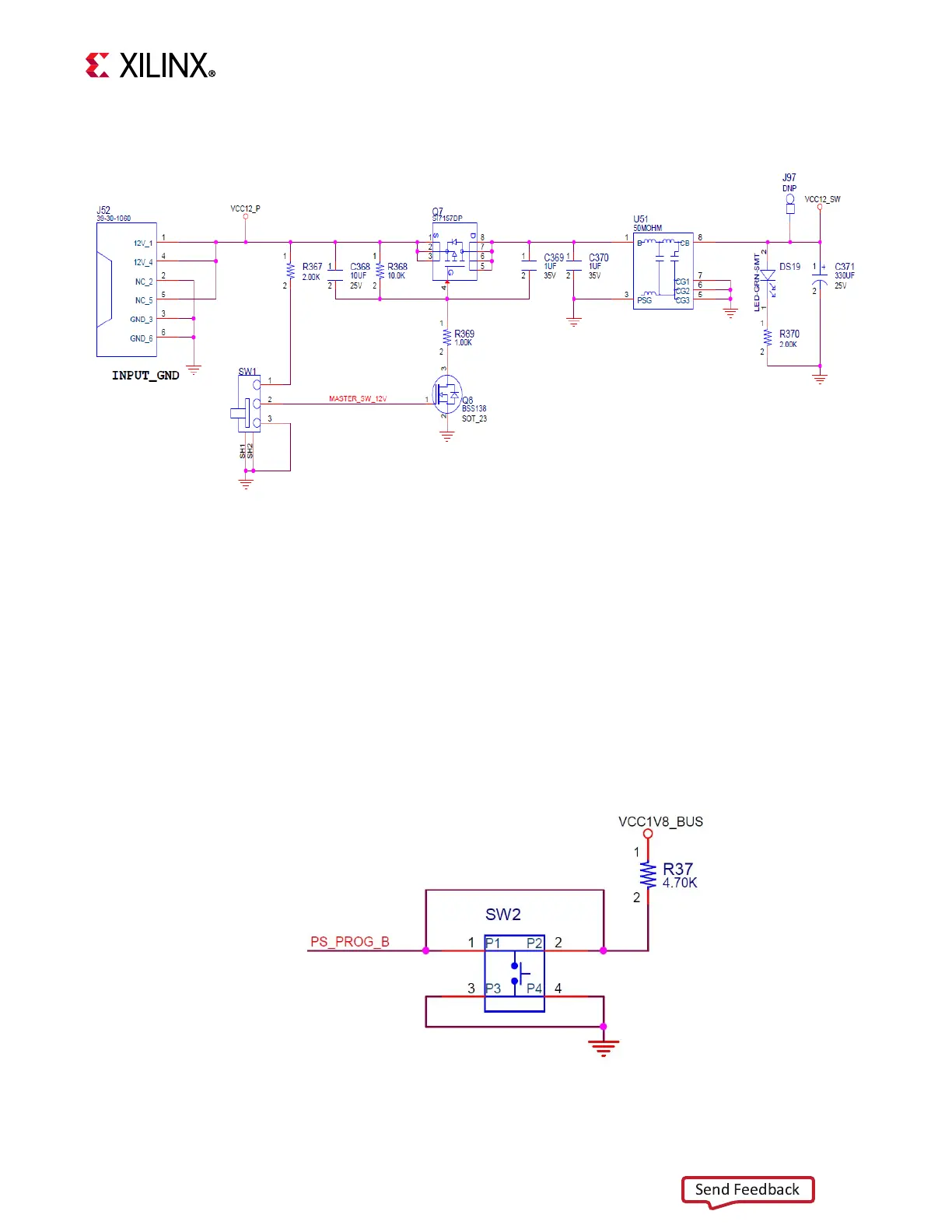
Figure 3-34 shows the power connector J52, power switch SW16, and LED indicator DS19.
Program_B Pushbutton
[Figure 2-1, callout 31]
PS_PROG_B pushbutton switch SW2 grounds the XCZU28DR RFSoC PS_PROG_B pin AA27
when pressed (see Figure 3-35). This action clears the programmable logic configuration,
which can then be acted on by the PS software. See the Zynq UltraScale+ Device Technical
Reference Manual (UG1085) [Ref 3] for information about Zynq UltraScale+ RFSoC
configuration.
X-Ref Target - Figure 3-34
Figure 3-34: Power Input
X-Ref Target - Figure 3-35
Figure 3-35: PS_PROG_B Pushbutton Switch