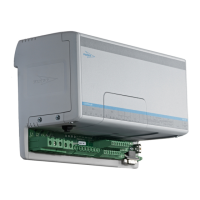
L1/L L2/N L3 U V W + B
A
WS003682
Figure 5: Frame size 2–3
1
L1 L2 L3 U V W
+DC -DCBR
2 3 4 5 6 7 8 9 10 11 12 13 14 15 16 17 18
WS003594
Figure 6: Frame size 4–6
3. Connect a lead between the following terminals:
The connections must be performed to get the drives to run.
a) Connect terminals 1 and 12 on both drives.
L1/L L2/N L3 U V W + B
1 2 3 4 5 6 7 8 9 10 11 1213
WS003650
Figure 7: Frame size 2–3
1
L1 L2 L3 U V W
+DC -DCBR
2 3 4 5 6 7 8 9 10 11
12
13 14 15 16 17 18
WS003597
Figure 8: Frame size 4–6
b) Connect terminals 13 and 9 on both drives.
L1/L L2/N L3 U V W + B
1 2 3 4 5 6 7 8 9 10 11 12 13
WS003651
Figure 9: Frame size 2–3
1
L1 L2 L3 U V W
+DC -DCBR
2 3 4 5 6 7 8 9 10 11
12
13 14 15 16 17 18
WS003598
Figure 10: Frame size 4–6
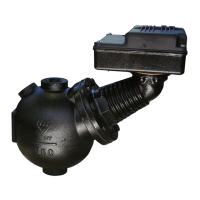
4. Connect the pumps sensor leads:
a) Twist the leads to minimize the electromagnetic noise in the signal.
b) Connect the T1 and T2 leads to control terminals 1 and 6.
Electrical Installation
SRC 311 - SmartRun
™
Installation, Operation, and Maintenance Manual 23