26
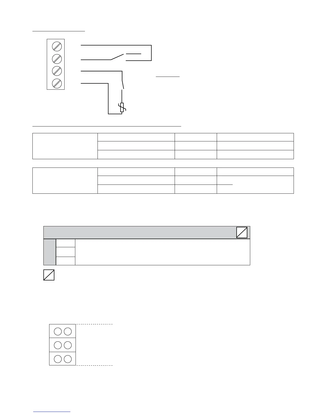
Connection Example
External switch to enable the
SOLO RUN (Hand Mode)
Example:
Low water or other
emergency off switch
Thermistor
(mounted in the motor terminal box)
Recommended connections of external protective devices:
Basic drive Thermistor X1/PTC
Emergency switch X1/PTC As described above
Low water switch X1/PTC
Master drive Thermistor X1/PTC As described above
External release X3/7-8
On the control card
Low water switch X3/11-12
When the HYDROVAR is used as a Basic drive in a multi-pump system, the X2 terminals on the power unit are
used for the serial RS-485 connection to the other HYDROVAR units in the system. (Note: Internal interface is
not available on Single Inverters!)
X2 RS485-Interface – Power Unit
X2/ SIO - Internal SIO-interface: SIO-
Internal interface
SIO+ Internal SIO-interface: SIO+
for multi-pump-systems
GND GND, electronic ground
……. Terminals not available for HYDROVAR Single drives
The internal RS-485 Interface on the power unit is used for the communication between up to 8 HYDROVARs
in a multi-pump system (minimum 1 Master drive). Use the same terminals to continue on to the next
HYDROVAR if required. Terminals X4/4-6 can also be used for RS-485 communication on all Master drives.
X2
GND
SIO + RS485 – internal interface
SIO -
X1
SL
SL
PTC
PTC
SW 1
Auto
Manual
S
S
}
ELECTRICAL INSTALLATION AND WIRING