5
Section 2
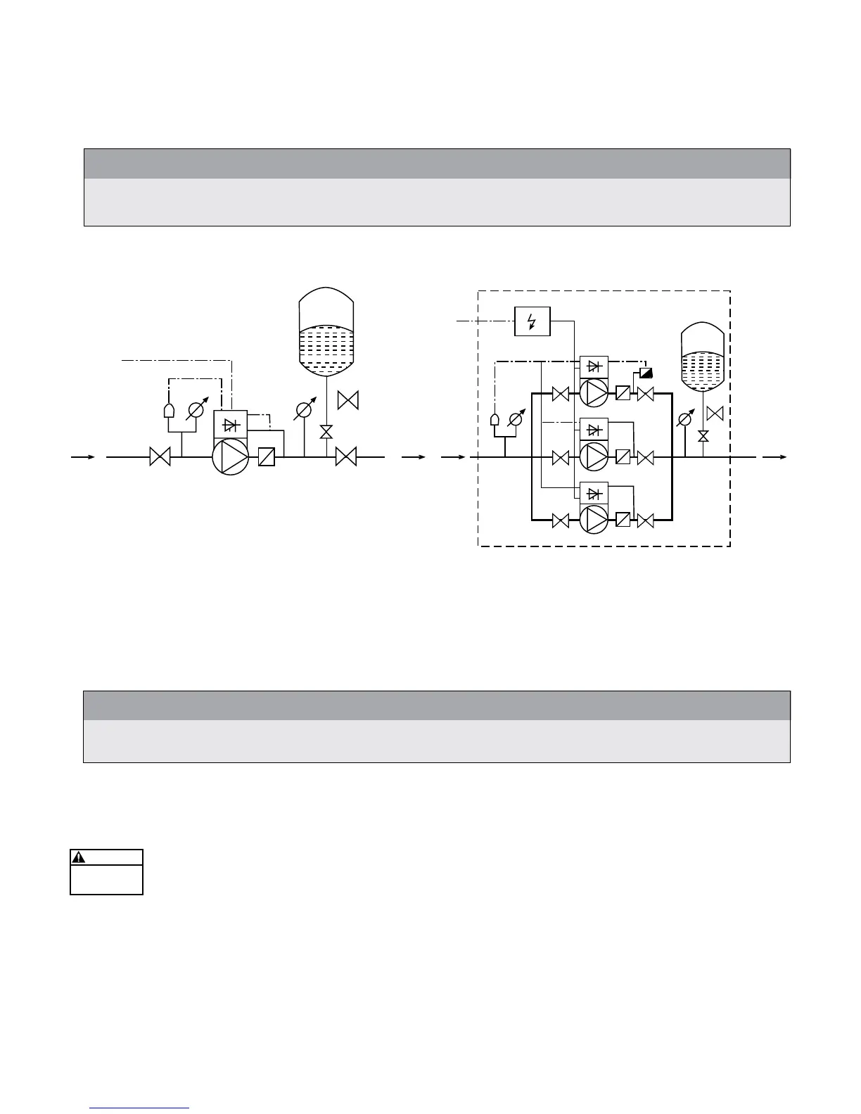
The following diagrams show typical single and multi-pump systems using the HYDROVAR Variable Speed Drive.
Connect directly to water supply. Use of a low suction pressure switch is recommended.
NOTE
Systems MUST be designed by qualied technicians only and meet all applicable state and local code re-
quirements.
Single Pump Layout Multi-Pump Layout
(1) pump with HYDROVAR (4) gate valve (7) pressure gauge
(2) diaphragm tank (5) check valve or ball valve (8) pressure transducer
(3) fusible disconnect (6) low suction pressure switch (9) pressure relief valve
General
NOTE
All plumbing work must be performed by a qualied technician. Always follow all local, state and provincial
codes.
A proper installation requires a pressure relief valve, a ¼" female N.P.T. threaded tting for the pressure sensor,
and properly sized pipe. Piping should be no smaller than the pump discharge and/or suction connections.
Piping should be kept as short as possible. Avoid the use of unnecessary ttings to minimize friction losses.
Some pump and motor combinations supplied with this system can create dangerous pressure.
Select pipe and ttings according to your pipe suppliers’ recommendation. Consult local codes for
piping requirements in your area.
All joints must be airtight. Use Teon tape or another type of pipe sealant to seal threaded connections. Use
caution when using thread sealant as any excess that gets inside the pipe may plug the pressure sensor.
Galvanized ttings or pipe should never be connected directly to the stainless steel discharge head or casing as
galvanic corrosion may occur. Barb type connectors should always be double clamped.
1
445
4
67 7
8
9
2
4 45
1
8
4 45
1
8
6
7
4 45
1
8
3
2
4
9
7
SYSTEM DESIGN