34
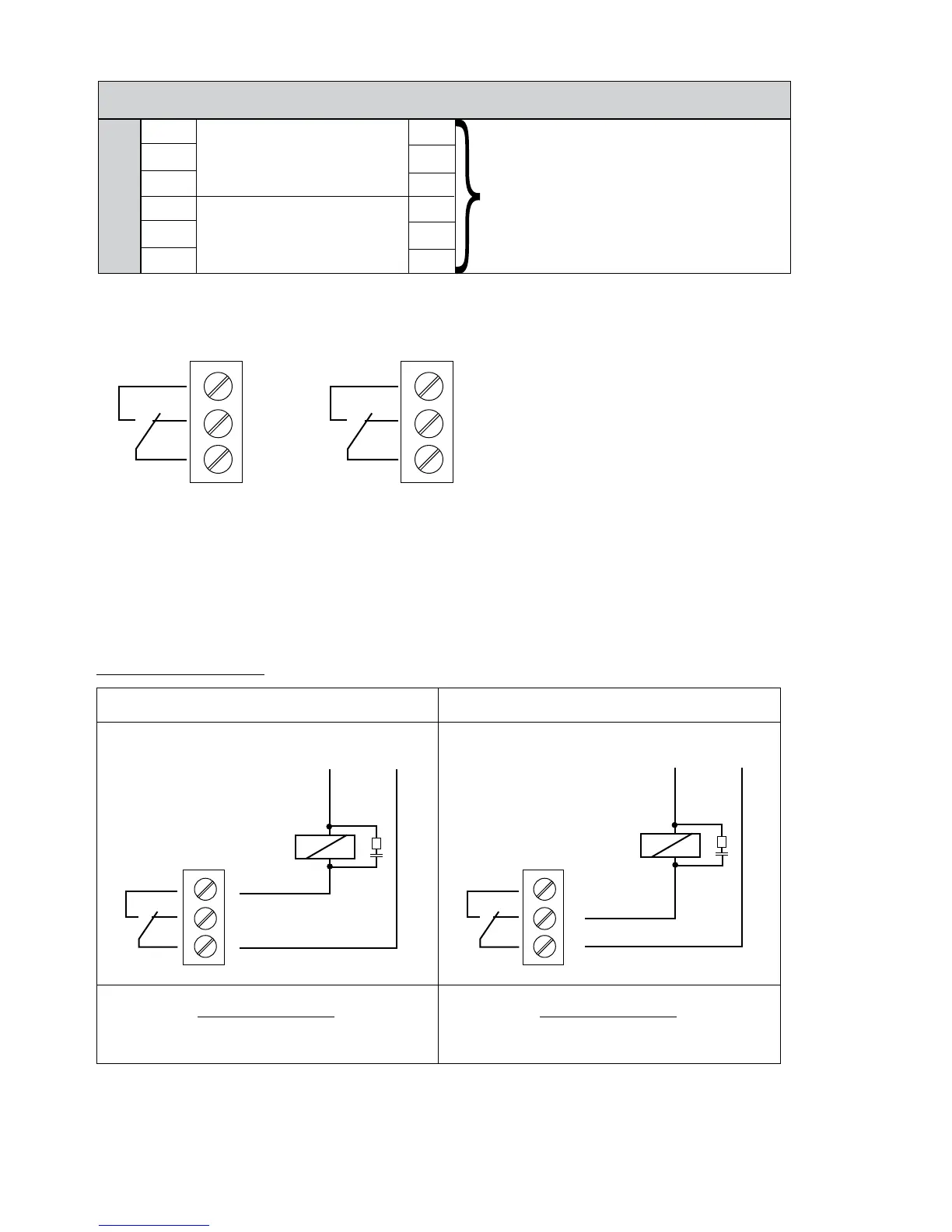
X5 Status-Relays
X5/ 1 CC
2 Status Relay 1 NC
[Max. 250VAC] [250mA]
3 NO
[Max. 220VDC] [250mA]
4 CC
[Max. 30VDC] [2A]
5 Status Relay 2 NC
6 NO
Status Relay 1 Status Relay 2
Notice:
Do not transmit any voltage or
electronic noise on these contacts.
Status Relay 1 is programmed for "Pump Run" when closed between terminals 1 and 3.
Status Relay 2 is programmed for "Fault" when closed between 4 and 5.
Factory setting: The output relays are used to signal pump-running or fault-signal.
See connection example below (To program see parameters
CONF REL 1 [0715] and CONF REL 2 [0720]).
Connection examples:
Pump Run Signal Fault Signal
X5/ 1 and 3 closed: X5/ 4 and 5 closed:
- motor run indication - signals a fault/error
X5X5
6 NO
5 NC
4 CC
3 NO
2 NC
1 CC
X5
X5
6
5
4
3
2
1
Ext. 250VAC / 220VDC Ext. 250VAC / 220VDC
ELECTRICAL INSTALLATION AND WIRING