en - Original instructions
e-SV series - Installation, Operation and Maintenance Manual 13
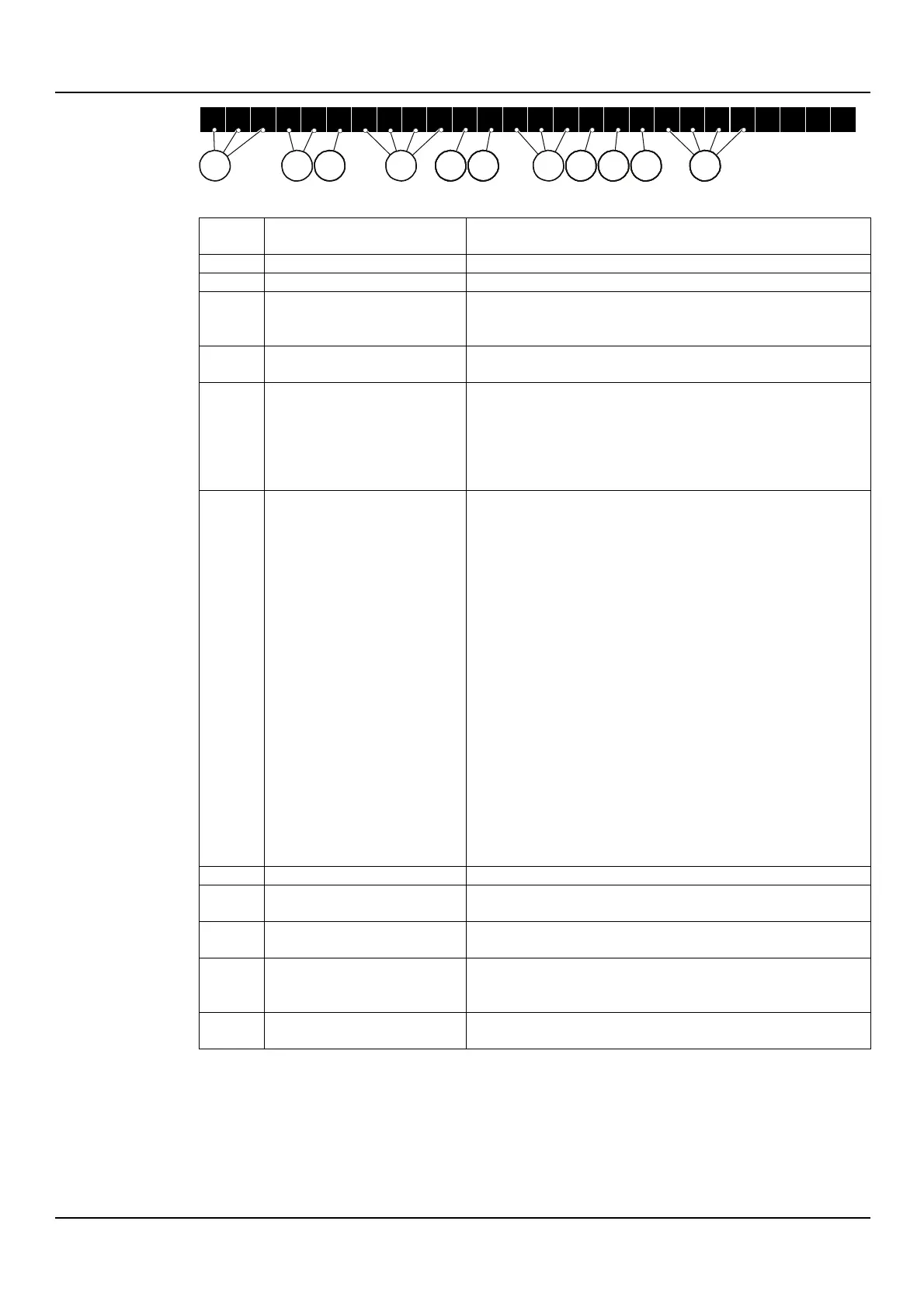
Figure 7: Identification code for models 33, 46, 66, 92, 125SV
Empty = standard
H = with Hydrovar®
X = other drivers
8/2A = 8 impellers, 2 of which with a smaller external
diameter, type A or B
G = AISI 304/Cast iron, round flanges (PN16/25/40
depending on model)
N = AISI 316, round flanges (PN16/25/40 depending on
model)
P = AISI 316, round flanges (PN 40)
X = custom version
Empty = standard
L = Low NPSH, round flanges, PN 25 (versions G, N)
H = high temperature 150°C, round flanges, PN 25
(versions G, N)
B = high temperature 180°C, round flanges, PN 25
(version N)
E = passivated and electropolished ( version N)
W = high temperature 150° and low NPSH (versions G,
N)
Y = high temperature 180° and low NPSH (version N)
U = passivated, electropolished and low NPSH ( version
N)
I = high temperature 150°, passivated and electropolished
(version N)
S = high temperature 180°, passivated and
electropolished (version N)
A = high temperature 150°, passivated, electropolished
and low NPSH (version N)
D = high temperature 180°, passivated, electropolished
and low NPSH (version N)
X = custom version
Empty = 2 poles
4 = 4 poles
Empty = pump only
M = Single-phase
T = Three-phase
Empty = standard version
Other = see technical catalogue
Marks of safety approval
For products with a mark of electrical-related safety approval such as IMQ, TUV, IRAM, etc.,
the approval refers exclusively to the pump unit.
EHM_M0006_A_sc
1 2 5 S V 8 / 2 A G L 5 5 0 4 T
12
1 1 1
111
1 3 65
1 1 1
4 7
8 9 10

 Loading...