FT-920 Operating Manual
15
Interconnection with non-QSK Amplifiers
(Yaesu FL-2100 Series or others)
The TX GND jack on the rear panel of the transceiver
provides for Tx/Rx switching of non-QSK amplifiers.
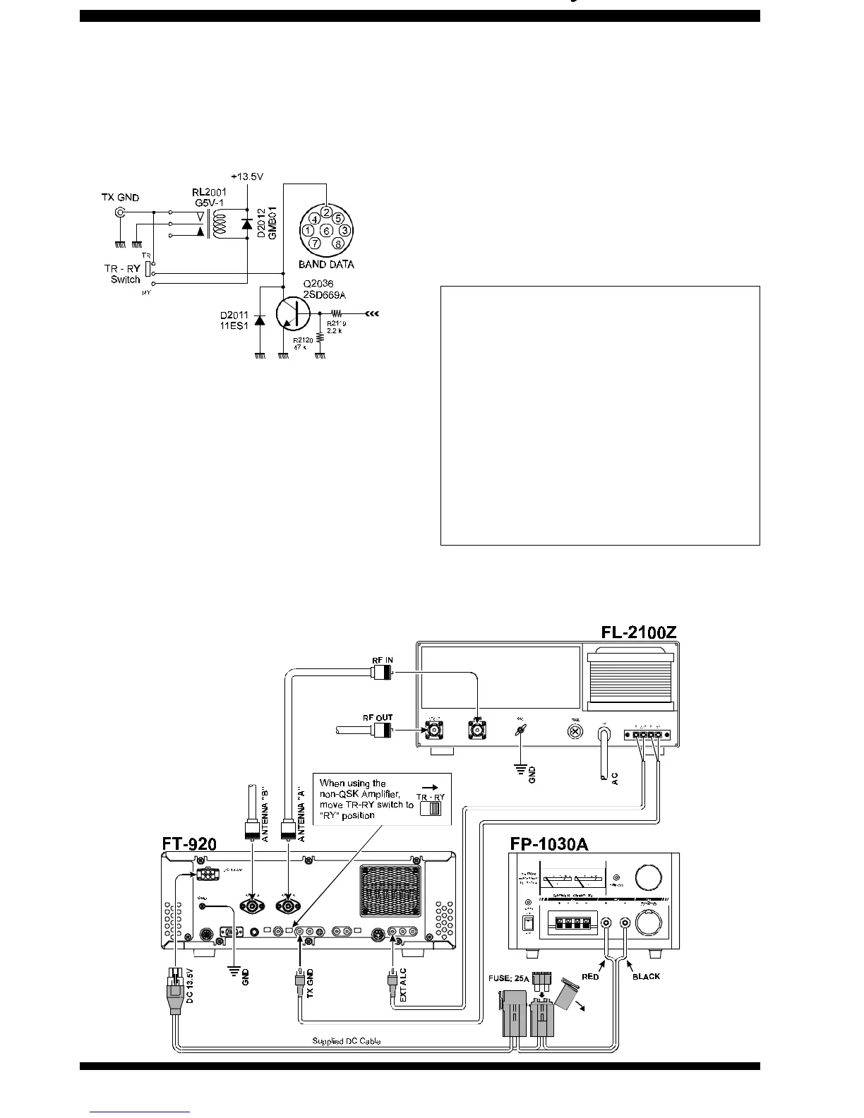
A schematic diagram of the FT-920’s internal relay
circuit is shown below.
As the FT-920 is supplied from the factory, the inter-
nal relay is disabled, and a high-dissipation NPN
transistor’s (open) collector is connected to the T
X
GND jack. To enable the relay for use with amplifiers
requiring it, move the rear panel TR-RY switch, lo-
cated in the hole near the center of the rear panel, to
the RY position. Use a thin, insulated object like a
toothpick to move the switch. Then connect the cen-
ter contact of the T
X GND RCA jack to the amplifier’s
relay control line, using the outer contact of the TX
GND jack for the shield. Connect the RF coaxial cable
and, if compatible, the ALC cable as described in the
QSK amplifier interconnection section above. Refer
to the drawing below for details.
With the relay enabled, the FT-920 can support
non-
QSK
linear Tx/Rx switching voltages of up to 220 VDC
(maximum permissible DC voltage) at 270 mA, 30
VDC at 2 A, or 125 VAC (maximum permissible AC
voltage) at 500 mA.
Caution!
Do not exceed the maximum ratings of the
switching circuitry (transistor or relay) of the
FT-920 made available via the BAND or TX GND
jacks. Your warranty does not cover damage
caused by improper interconnections to linear
amplifiers. When in doubt, it is always safest
to utilize the TX GND jack with the TR-RY switch
set to TR, as this configuration should handle
the switching requirements of most all com-
monly-available amplifiers.






 To Next Page