FT-920 Operating Manual
35
Before You Start
Before you begin operation for the first time, preset
the front panel controls and switches to the following
positions:
POWER, VOX, MOX: all off
MIC GAIN: 9 o’clock
AF GAIN: 9 o’clock
RF POWER: fully clockwise
RF GAIN: fully clockwise
SHIFT: 12 o’clock
NR: 12 o’clock
LOW CUT: fully counter-clockwise
(approximately 7 o’clock)
H
IGH CUT: fully clockwise
(approximately 5 o’clock)
SQL: fully counter-clockwise
PROC LEVEL: fully counter-clockwise
MONI LEVEL: fully counter-clockwise
NB LEVEL: fully counter-clockwise
SPEED: 12 o’clock
PITCH: 12 o’clock
SIDE TONE: 12 o’clock
These represent typical starting points for operation;
optimum setting procedures will be discussed later.
Note that a wide variety of transceiver characteris-
tics may be optimized or adjusted using the Menu
System, discussed in detail beginning on page 69.
Connect your microphone and CW key/paddle to the
appropriate jacks, then turn on your 13.5 Volt DC
power supply.
Receiving
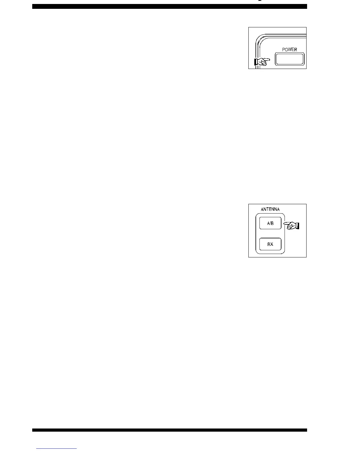
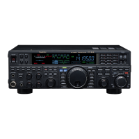
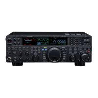
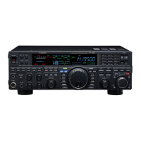
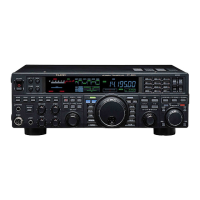
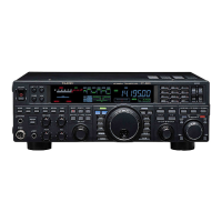
Press the POWER switch to
turn the transceiver on. As-
suming that this is the first
time you have used the FT-
920, the display should look
like this:
Inspection of the display will show you that both VFO-
A and VFO-B are set to 7.000.00 MHz in the LSB
mode. The (Green) [RX] and (Orange) [TX] LEDs
associated with VFO-A should both be illuminated,
indicating that all frequency control is being exercised
by that VFO.
You should now be hearing background noise. Ad-
just the AF GAIN control for a comfortable listening
level on the incoming background noise.
We will now discuss antenna selection, frequency
navigation, and other aspects of FT-920 operation.
Antenna Selection
Two main antenna jacks
are provided on the rear
panel of the FT-920, allow-
ing you to connect, for ex-
ample, a triband Yagi to one
jack and a multiband dipole
or vertical to the other.
These “SO-239” or “M” type jacks, labeled A and B,
may be selected by pressing the ANTENNA A/B switch
on the left side of the transceiver’s front panel. This
switch toggles between the two available main an-
tenna ports.
Note that the maximum power output for each an-
tenna jack may be set independently via Menu Items
U-49 (Antenna A) and U-50 (Antenna B). See page
79 for details.
An additional receive-only antenna jack (RCA type)
may also be found on the rear panel of the trans-
ceiver, labeled RX IN. This jack may be connected to
a specialized antenna, such as a loop or Beverage,
for use in the receive mode; transmission will remain
on the previously-selected A or B antenna if a re-
ceive-only antenna is used.






 To Next Page