FT-920 Operating Manual
32
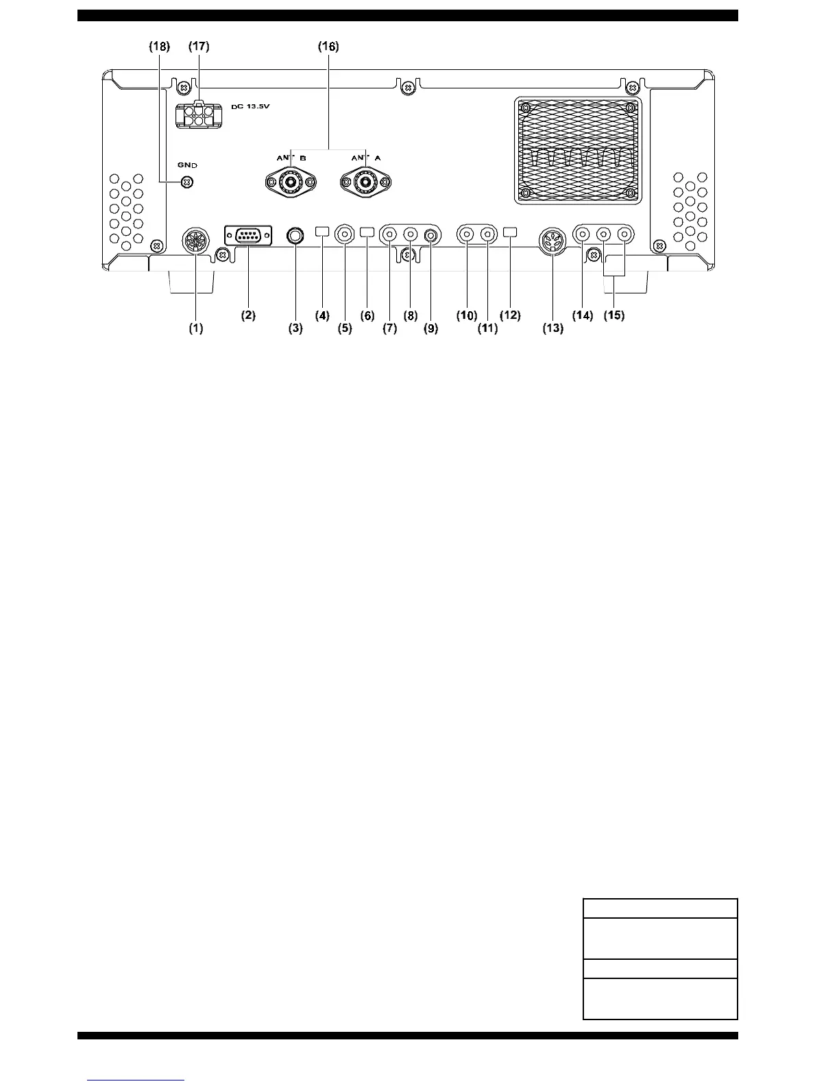
(1) BAND Connector
This 8-pin interlocked DIN connector includes Tx/Rx
switching and bandswitching control lines for use with
the Yaesu Model FL-7000 Linear Amplifier.
(2) CAT Port
This DB-9 connector is used for interconnection to a
personal computer’s serial port to enable computer-
assisted operation. Use a standard (not “null modem”)
RS-232C serial data cable.
(3) KEY Jack
This jack may be used for connection to a straight
key, an external electronic keyer, a computer-driven
CW keying interface, or a keyer paddle.
(4) PDL-KEY Switch
This switch changes the function of the
rear-panel
KEY jack.
When the “PDL-KEY” switch is set to the “PDL” posi-
tion, the rear-panel KEY jack will be connected in par-
allel with the front-panel KEY jack; when the “PDL-KEY”
switch is set to “KEY,” the
rear-panel
Key jack will be
changed so as to accept a straight key, external elec-
tronic keyer, or computer-driven keying interface
while
simultaneously allowing the front panel K
EY
jack to
be connected to a keyer paddle for utilization of the
built-in Electronic Keyer.
See page 18 for configura-
tion details and operating tips.
(5) PTT jack
This “RCA” female connector is used for connection
of a footswitch or other external switch for Tx/Rx com-
mand control of the FT-920. This jack is wired in par-
allel with the front-panel MOX switch; shorting the
PTT jack to ground causes the FT-920 to be placed
in the Transmit mode, while opening the connection
to the PTT jack returns the radio to the Receive mode.
Open-circuit voltage is 13.5V DC, and short-circuit
current is 15 mA.
(6) TR-RY switch
This switch selects the switching device to be con-
nected to the (adjacent) TX GND jack, used for Tx/Rx
control of peripheral devices such as linear amplifi-
ers, etc. With the switch set to the RY position, the TX
GND jack is connected to a mechanical relay; if the
switch is set to TR, the TX GND jack is connected to a
switching transistor. The specifications for these de-
vices are shown in the next section.
(7) TX GND Jack
This RCA connector is connected to the switching
device described above, for control of external de-
vices. Please note the specifications for the two de-
vices available via this jack:
The relay provides a me-
chanical closure to
Ground on Transmit,
while the (NPN) transis-
tor switch sinks its (open)
collector to ground on
RY
60 Wa tts max imum
(AC 125V max. at 50 0 mA,
DC 220V max. at 270 mA)
TR
25 Wa tts max imum
(
Positive DC Voltage Only
, 50 V
max. at 500 mA)








 To Next Page